How to reduce co-channel interference

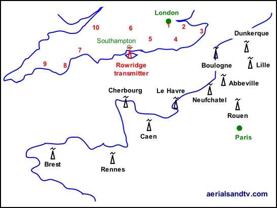
Co-Channel interference is when your aerial picks up two transmitters (TXs) both broadcasting on the same frequency and it is never something any aerial installer welcomes..... The transmissions can both be from within the UK just as much as they can be from abroad, and the latter is what those on Rowridge TX can suffer from, particularly under high pressure conditions, also known as "lift" conditions. In general these conditions have the most effect at lower UHF frequencies so group A will tend to be affected more than group C/D. Radio is even more affected because the frequencies are lower, particularly when one gets down to MW. The map below shows the location of the major sources of co-channel from French transmitters, though there are of course more transmitters further North in Belgium and Holland. Many other locations can suffer from co-channel from continental broadcasts if their aerials face South or East, even homes in Sheffield (which is in the middle of England ! ) can get continental co-channel if they’re aligned onto Belmont, i.e. their aerials face East. Bear in mind that the nearest country (East) past Belmont is about 200 miles past it !
When UHF TV started in this country the transmission planners did their best to minimise co-channel interference by assigning different groups to adjacent main transmitters, though, of course, the other main reason for this was to allow the use of more efficient grouped aerials. To take Emley Moor (a B group) as an example, the four nearest transmitters were Bilsdale (A group), Waltham (C/D group), Belmont (A group) and Winter Hill (which is admittedly on the other side of the Pennines) a C/D group. If TXs of the same group had overlapping coverage areas then the broadcast frequencies would be chosen to avoid co-channel, e.g. Rowridge Channel Allocation Guide.
Differing transmission polarities are also used to try and minimise problems from co-channel, and since its 2012 digital switchover Rowridge transmits both polarities to give people the option to minimise co-channel. Bear in mind that a vertically polarised aerial will be more susceptible to picking up off beam transmissions (the main cause of ghosting and co-channel interference) because to a certain extent, to those broadcasts from the side the antenna is effectively a vertical dipole.
Let me be quite honest here, co-channel interference can be a pig to solve. All the techniques advocated here are correct in theory, but RF is a Black Art. They may work, they may not..... There are three main weapons in the fight against co-channel, aerial positioning, attenuators and "high gain aerials", particularly (if it’s possible to use one) a grouped aerial . The latter two would usually be utilised, somewhat bizarrely, together. This is because an attenuator on its own cannot increase the difference in the signal levels received from each transmitter, the ratio between the wanted and unwanted signal levels will stay the same. There isn’t much reason, theoretically, why an attenuator would work on its own, but it does work sometimes, and because they’re cheap and easy to try I’d always give it a go. They’re more likely to be effective under "lift" conditions (i.e. high pressure) when the level of all the received signals has risen, and thus it may also be causing cross modulation interference in the tuner (and/or amp). What we’re always trying to do is increase the amount of signal collected from the required transmitter, whilst reducing the amount from the unwanted transmitter. An amplifier is not what’s wanted at all, since it’d amplify both transmitters equally, in fact it would probably make things worse, particularly if the site is in a strong signal area.....

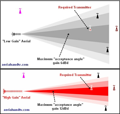
Here we have a graphic illustrating typical co-channel problems. The top one shows the kind of acceptance angle you’d get with a "low gain" aerial, whereas the bottom one shows the same but with a "high gain" aerial. Note how the the acceptance angle is narrower on the "high gain" aerial, that’s why it’s a high gain aerial ! (see Polar Response Diagrams).
The reason the high gain aerial is in red is to represent an A group antenna, which is the one you should use with Rowridge, which is an A group TX ! Therefore a Yagi18A, an XB10A or (ultimately) an XB16A would be a good choice.
If the offending transmissions are coming from behind your aerial try using an antenna with a high rejection of signals from the rear, i.e. a Log Periodic or, particularly, a Grid. Alternatively try to site the aerial where it’s shielded from the miscreant transmissions, e.g. down the side of your house or on the other side of the chimney.
If the unwanted transmitter is to the side of the alignment onto the required TX, the first option is to try and resite aerial so it’s shielded from the unwanted transmissions, see above,
The next option is the use of an attenuator. The setting of the latter may need altering under different weather conditions. Note that an attenuator on its own cannot increase the difference in the signal levels received from each transmitter, it can only reduce both signal levels equally. Thus an attenuator works best in conjunction with a high gain aerial (even if already in a strong signal area) to increase the difference in the signal levels from each transmitter. If we say, just for the sake of argument, that the unwanted transmissions are being received at 0dBd (which is not zero signal remember, it’s just the amount of signal collected by a dipole on its own) the difference between our low and high gain aerials [in the above graphic] would be 12dBd to 6dBd. That is to say that the difference in the signal levels (between the wanted and unwanted transmissions) from the high gain aerial would be 6dB more than from the low gain one. And that’s a big difference. If the unwanted transmitter is just "off beam" of the wanted one you’ve more of a chance of minimising co-channel then if it’s directly inline and behind the required one. The use of an attenuator in conjunction with a "high gain" aerial, is the way to go, see above. As the graphics above show a high gain aerial with its narrow beam width is less likely to pick up the unwanted transmissions than a "low gain" aerial with its wider acceptance angle.
You can also try aligning your aerial slightly to one side of the required transmitter in an attempt to avoid the unwanted broadcasts, this has more chance of working if your antenna is a high gain one. If it makes no difference one way, try the other way ! You could even try altering the tilt of the aerial. There’s no particular reason why this should work but RF is a Black Art, if you’re desperate you should try anything. What have you got to lose, apart from your time, or sanity.
As Bill Wright would say, "proceed empirically" a posh way of saying forget theory, it’s what actually works that counts, suck it and see.
If the transgressing transmitter is directly in line with the wanted one, you’ve got big problems. In the case of Rowridge you can experiment using vertical polarity. Other than that the $64,000 question is : is there a different transmitter you can use !
French co-channel interference problems

The numbers in red are other UK transmitters which can also be affected by co-channel interference from French broadcasts :
1 Crystal Palace
2 Bluebell Hill
3 Dover
4 Heathfield
5 Midhurst
6 Hannington
7 Stockland Hill
8 Beacon Hill
9 Caradon Hill
10 Mendip
Above are the French Transmitters that tend to give the most co-channel interference problems with UK TV transmitters, as advised by Ofcom.
Post switchover Rowridge (uniquely) be transmits in vertical as well as horizontal polarity in order to lessen the chances of co-channel interference. The aim is to give people the option to use either polarity and therefore take advantage of cross polar rejection to help reject the unwanted transmissions.
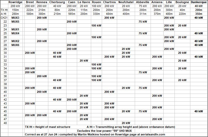
Channel Allocation Guide for the French Transmitters most likely to give co-channel problems with UK broadcasts, namely, Brest, Rennes, Cherbourg, Caen, Le Harvre, Rouen, Neufchatel, Abbeville, Lille, Boulogne and Dunkerque.
The table excludes the low power "R9" UHD MUX, details of the latter can be found here [link]
The information in the table was correct as of 27 Jun 24. Our thanks to Martin Watkins for undertaking the research.


