Transmitters
Note, due to the new phenomenon of MUXICAL chairs you may experience problems with certain MUXES disappearing. First try rescanning your TV / set top box, do it manually if possible. If this fails to sort it check on transmitter work or call the reception advice phone numbers.
Also see basic digital fault finding.
Subject list :
List of transmitters on this site
General transmitter features
Transmitter relative heights incl:
- Time to fall from the top
Most powerful TV transmitters
Analogue v digital transmission power
Which transmitter am I on ?
Coverage maps / reception predictors incl:
- Freeview UK postcode predictor
- Actual signal levels
Transmitter Radiation Patterns
i.e. is it transmitting in your direction?
Single Frequency Networks (SFNs)
Problems with your transmitter ?
Also see 6 MUX Transmitters.
List of transmitters on this site
Belmont
Bilsdale
Black Hill
Bluebell Hill
Chesterfield
Craigkelly
Crystal Palace
Emley Moor
Hannington
Heathfield
Holme Moss (FM /DAB radio)
Mendip
Moel Y Parc
Moorside Edge (MW radio)
Nottingham
Oughtibridge (a typical repeater transmitter)
Oxford
Pontop Pike
Ridge Hill
Rowridge
Sandy Heath
Sheffield / Crosspool
Sudbury
Sutton Coldfield
The Wrekin
Waltham
Winter Hill
General Transmitter Features
As at the end of the 700MHz clearance (early 2020) there are around 1126 * TV transmitters in the UK all listed here (downloads an Excel file : courtesy of Martin Brown). Of those transmitters 50 are “main” transmitters (e.g. Crystal Palace), and 30 are larger repeaters (e.g. Sheffield). Together these make up the 80 original digital transmitters, plus there were 12 more 6 MUX transmitters added during the 700MHz clearance (2017 to 2020). The remaining transmitters are mainly smaller repeaters (e.g. Oughtibridge) which only transmit the 3 main PSB MUXES, though to be fair that’s most of the channels the majority of people watch.
* excludes “self help” transmitters, it also counts dual polarisation transmitters and those with two different regions (which may even be transmitted in different directions) as only one transmitter.
Antenna arrays : (main transmitters) Waltham.
Antenna arrays : (relay/repeater transmitters) Oughtibridge.
Antenna arrays : (manufacturers) ROHN and RFS
Log Periodic Aerials on the repeaters : details of the Chelton GD2000.
Base of masts : (cylindrical) Belmont and (spaceframe) Ridge Hill including figures for the weight of masts and details of self supporting towers.
Building a guyed mast :
- Constructing stayed masts (MB21)
- How Holme Moss was built (video, external link)
- Mendlesham : the first 1000ft mast erected in the UK in 1959 (video, external link)
How high is high ? :
- Ascent of Winter Hill transmitter with helmet cam
- Man on a mission at Sandy transmitter.
Feeder cables : Waltham’s feeder cables (including “duplication”).
Mast stays : They aren’t straight ( ! ) and the anchor blocks
Painting Bilsdale transmitter : “The Bosun’s Chair” system used and details of the type of paint finish used.
Population coverage : TV transmitters and FM transmitters
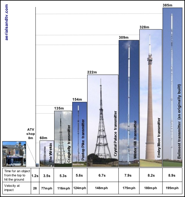
Transmitter Relative Heights (and how long to fall from the top.....
Just how big would Emley Moor transmitter (TX) look next to Belmont (as originally built) ?
How big would one of the shorter TXs, like The Wrekin, look next to Belmont ?
Just how small would our shop look next to the shortest of the main TXs, The Wrekin ?
Notes
All the pictures of the transmitters (TXs) are to scale.
The heights of the structures are estimates. Different sources give different heights, some of which seem to include the transmitting array(s) at the top, and others don’t. In fact the only mast which I’m certain of the height is Waltham, because I’ve seen the actual plans for the layout of its transmitting antennas ! Belmont is a similar design but it’s even taller and has six sets of stay levels, or did have till they shortened it up to April 2010.
The height of our shop is to the top of the roof.
I was going to put an extra line in "Number of Asprin required if the object hit you", but there were too many variables. For instance, would a child need Junior Asprin ?
Time to fall from the top......
The times in the above table for the object to hit the ground are calculated in free space. Obviously these structures are not built in vacuums, but if the object being dropped was made of a dense material (like a spanner for instance....) I wouldn’t have thought the calculated figures would be that far out. In fact, in August 2011, John Sager did some calculations (of the time and velocity reached) taking into account the effect of air resistance/drag. The example was of a spanner, a 19mm combination spanner (weight 138g) in fact. To simplify matters it was assumed that the drag was similar to a piece of metal strip 225mm x 20mm x 5mm, these equate to the average dimensions of the spanner. John did two sets of calculations, the first if the spanner was falling "end on", and the second if it were falling "side (flat) on". This makes a big difference because the drag is proportional to the frontal area of the object. [link]
For what it’s worth I reckon the spanner may well fall open end first because there’s more drag on the (opposite) ring end, and in addition there’s a weight bias toward the open end.
Note that provided the spanner falls "end on", the speed reduction in air (as opposed to in free space = a vacuum) is not that great, because its surface area is only 0.0001msq. However, when it falls (flat) "side on", and its surface area is 0.0045msq (i.e. 45x greater) the spanners maximum speed in air (its terminal velocity) is only 60mph. At low speeds, when dropped off our shop roof, the drag is relatively insignificant, it’s only at higher speeds that it becomes a major factor.
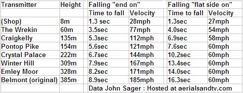
Whilst John was at it he also worked out the time to fall and the speed at the bottom for Taipei 101 and the Burj Dubai.

John actually went further and calculated the effect that the differing density of the air would have on the velocity reached by the plunging spanner. As can be imagined the varying air density had far more of an effect when falling "flat side on", in fact John reckons said spanner, if dropped off Taipei 101, would actually be travelling slightly quicker (60.5mph) after falling 211m, than it would be when it made a hole in the ground (at 59.5mph) !
Now I’m guessing here, but I reckon anyone who doesn’t find that interesting probably didn’t do Physics at school.....
Relative heights of the other main transmitters on this site.
Belmont - 385m (as originally built, now 351m)
Emley Moor - 328m
Waltham - 314m
Bilsdale - 309m
Winter Hill - 309m
Black Hill - 307m
Mendip - 280m
Moel Y Parc - 240m
Sandy Heath - 240m
Holme Moss - 228m
Sutton Coldfield - 225m
Crystal Palace - 222m
Oxford - 160m
Ridge Hill - 160m
Sudbury - 160m
Pontop Pike - 154m
Hannington - 154m
Heathfield - 145m
Rowridge - 135m
Craigkelly - 135m
Also see How High is High ?
TV Transmitters : Top Twenty (one)
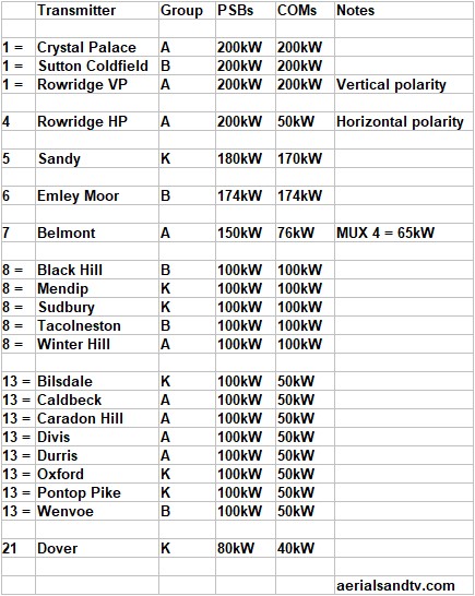
Which are the most powerful TV transmitters ?
(Also see Top 12 FM transmitters)
Just as a bit of fun I compiled this "Top Twenty (one)". The power levels are often different for the PSB MUXES (1 to 3) and the COM MUXES (4 to 6), but I’ve given precedence to the former because far more people watch them, and the programmes on them are (slightly) less likely to be crap, or repeats....
Which TV transmitter am I getting my signals from ?
The simple way is to use the Digital UK coverage checker, but it isn’t 100% accurate, it takes no account of local conditions (e.g. tall trees or buildings)
When considering which transmitter to receive your signals from always remember the critical factor is “Line Of Sight”, generally speaking this is far more important than which is the nearest.
If you’re already on a transmitter and just replacing your aerial then you can identify the transmitter from the frequencies (or channel numbers, note the difference ! ) of the programmes you have tuned in on your TV. The best way is to consult the Channel Allocation Guides of the transmitters we have a dedicated page. Alternatively use the Digital UK coverage checker.
If your aerial is vertically polarised it is almost certainly aligned on a repeater transmitter. All but two main transmitters are horizontal but bear in mind that some people have incorrectly polarised aerials !
However, not quite 100% of horizontally polarised aerials are on main transmitters, because a few repeaters are horizontally polarised ! ? !
If you’re trying to locate a new transmitter then bear in mind that TV aerials are very directional (particularly if they’re “high gain”) so the simplest way to find out which transmitter you may be on is by checking which way your antenna faces !
Alternatively, at your location, which way do most (or preferably all....) of the other antennas face ? This is a pretty reliable guide but it’s not infallible. We’ve occasionally done installs where every other aerial is utilising a particular transmitter (usually the nearest one......) with imperfect results, we’ve decided to try a different one and it’s come up trumps !
Now check on ATV transmitter Map or Main Transmitters map or MB21’s map page or Ofcom Maps
If there is more than one transmitter in a particular direction check if the polarity of the aerial(s) gives an indication as to which is the correct one.
You should bear in mind that some transmitters (mainly repeaters) have restricted radiation patterns, this is mainly to prevent co-channel interference with other TXs using the same frequencies, see article on transmitter radiation patterns. The Digital UK postcode checker knows whether the TXs radiation pattern is restricted in your direction !
Remember that if you are realigning your aerial (to test the signal from a different transmitter), you MUST retune your TV or you won’t get anything at all !
Coverage maps / postcode predictors
This site does not provide TV transmitter coverage maps because at best they are misleading and at worst they are downright inaccurate !
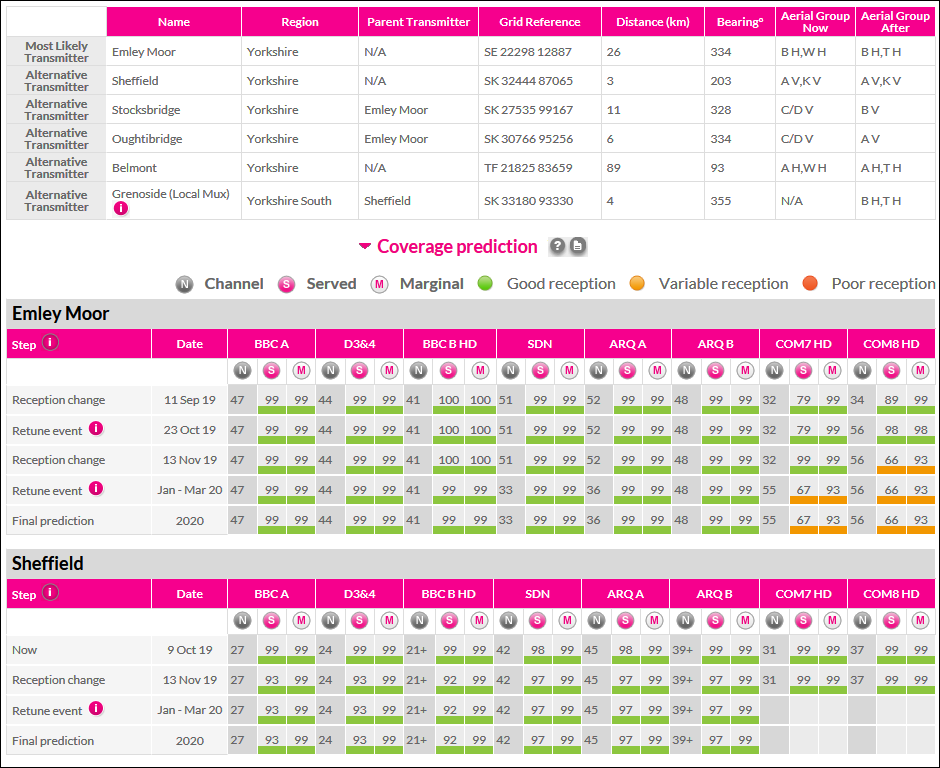
On a more general level the use of coverage maps and postcode predictors can be misleading because they do not (and in fact cannot) take into account local conditions (particularly trees or high buildings) and they tend to over emphasise distance to the transmitter. Any professional installer will tell you the over riding importance of the former and the relative lack of importance of the latter, see actual signal levels. For instance if a locality has a choice of two different main transmitters, one 10 miles away through a bleedin’ great tree (or high building) and one 40 miles away but with clear line of sight, any installer worth his salt will choose the latter of the two options.
One of the most amazing examples of the effect of line of sight and altitude was a customer near Bacup (north of Rochdale) who was actually on The Wrekin transmitter, near Telford ! That's 72 miles away..... Winter Hill transmitter was only 14 miles away and it transmits at 100kW (The Wrekin is "only" 10kW to 20kW), but, obviously, there was a soddin' great hill in that direction !
The Digital UK / Freeview postcode checker is the most widely used predictor.
The predictor is also very useful for getting all the current bang up to date information on a particular transmitter. All you have to do is put the postcode of the transmitter (or somewhere near it) into the system and all the relevant info is bought up. At one time (before the system was downgraded) I had direct links to all the transmitter predictions on my site. Unfortunately, very unfortunately, in Nov 2019 it became impossible to access these*, so sorry about that. In fact, for just over a year, you could not even directly access the only bit actually worth using, the "Detailed view", though fortunately that direct link was reinstated in March 2021. The "Detailed View" brings up far more information including any planned changes. Furthermore, by hovering the cursor over the channel number, it brings up the transmission power, which can be well worth worth knowing. Generally the predictor is a bit pessimistic, but not always…… The other problem with it is it doesn't warn of potential excessive signal which can sometimes be just as big a problem as insufficient signal.
*Exceptionally frustrating....... Incidentally have you ever noticed that most IT "upgrades" are actually "downgrades" ? Incredible as it may seem we have to remember that someone was actually paid good money to ruin the DUK / Freeview predictor !
Also worth trying, as much for interest as anything else, is this aerial alignment calculator, which also has a “site to transmitter topography profile”. Most people don’t know their latitude and longitude so, for your location (= “Where is the receiving aerial?”) click on the drop down tab and select postcode if required. There doesn’t appear to be a facility to enter your street number but your location can be moved when (later) you’re in the “map function”. The calculator sometimes appears to be reluctant to switch from “map” to “profile” (it seems fine in the other direction), if so just click “clear” and click straight onto “profile”. For the transmitter just click the drop down tab and then select the desired filter. Note that for our shop’s location the site to transmitter topography profile appeared to be overly pessimistic in its signal prediction, e.g. the shop (S6 2LL) gets a reasonably good signal off Emley Moor.
Post code predictions can sometimes be highly amusing, and this is particularly the case in sparsely populated areas where the geographical areas are larger, e.g. our test site. In fact a reception predictor (pre DSO) for our test site advised a “High Gain” or even an ’Amplified Extra High Gain’ aerial, yet even before the huge digital switchover power increase in 2011 the signal levels off Emley were too large, and that was off a DM Log !
Infamously we once got a call (pre switchover) from a customer near Owler Bar on the outskirts of Sheffield who’d been advised by the checker that she couldn’t get digital. But Owler Bar is over 1000ft in altitude, on the NE side of a mountain facing Belmont, so what do you think ? ! ? In fact she could probably have picked up the low power pre switchover signals from Bilsdale and Crosspool (Sheffield), with a chance of Emley Moor as well !
The table below tells its own story, try using some of the coverage predictors with these post codes, see how accurate, or not, they are !
And all this is off a relatively low gain DM Log aerial !
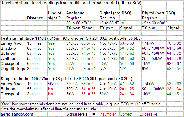
Just to put the above figures into perspective, post switchover you could put the Emley signal at the test site through a two way splitter (loss 4dB) with each leg feeding an eight way splitter (loss 12dB) which would give 16 points. Including, say, 3dB of cable loss the total loss would be 19dB, and the signal would still be on the borderline of being excessive !
Even the signals from Belmont (59 miles away) would comfortably feed an eight way splitter.
Down at the shop it’s a rather different story but even there the Emley signal could still feed 4 points if the cable runs weren’t too long, and two points if they were.
Well OK we do provide a link to a site page giving “coverage” for all the particular frequencies, mainly out of interest but also because it can be helpful in identifying possible causes of co-channel interference. I couldn`t work out if it was up to date though ! Also bear in mind that the vast majority of the repeater transmitters aren’t included on this map, e.g. Winter Hill’s repeaters. Use the linked map(s) in conjunction with the Channel Allocation Guides on our transmitter pages.
Transmitter Radiation Patterns
It’s very useful to know if the transmitter you’re thinking of using is actually transmitting full power in your direction. The Digital UK postcode predictor takes this into account, but, as we’ve already discovered, postcode predictors can be rather inaccurate. Now, as already discussed “the powers that be” are reluctant to tell people what direction the transmitter(s) actually transmit in. However, Brian Butterworth, like a white night on a rampant stallion, used the Freedom of Information act to get some of the radiation patterns released. Unfortunately many of the patterns have been withheld, and, worse, many of them are for the bigger transmitters used by the most people, although, to be fair, most main transmitters have Omni directional radiation patterns anyway.
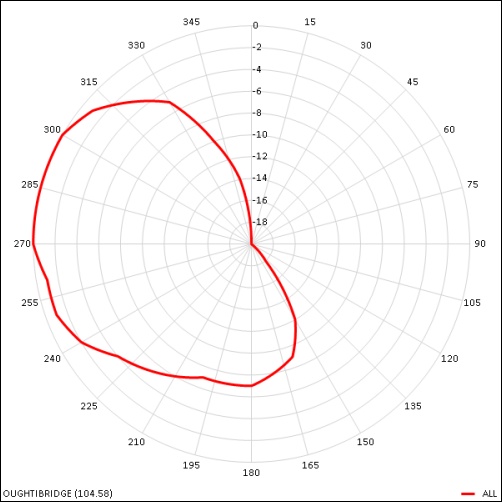
In the meantime Mike Dimmick was the first to actually convert the data into easily understood patterns, which are listed below by region. On each pattern the top (0 degrees) is North. The further towards the centre the pattern is (in any particular direction) the greater the attenuation of the signal in that direction, if it’s right on the edge of the outer circle that’s full power for that transmitter. However, it’s important to realise that even if the pattern is right towards the middle (i.e showing maximum attenuation) the transmitter will still be giving some signal out, it just means it’ll be harder to pick it up, particularly if the transmitter is one of the lower power relays and/or you’re in a poor signal area.
Below is the transmission radiation pattern of Oughtibridge.
When using the links, if necessary, click on "Show Albums" (on the left hand side of the linked to window)
As of 3 Feb 23 these appear to be unavailable, enquiries as to there whereabouts are ongoing !
Single Frequency Networks (SFNs)
A Single Frequency Network, or SFN, is when a number of transmitters all broadcast the same signal at the same frequency. The best example of this is the DAB network*, partly because a lot of car drivers use this service and it’d be annoying, and dangerous, if they had to continually retune their radios as they travelled between areas served by the various transmitters. However there are the odd examples of TV transmitters also using SFNs, the most significant being the group made up of The Wrekin, Bromsgrove and Lark Stoke.
But isn’t co-channel interference one of the big problems for signal reception ?
Well yes it is, but when utilising an SFN the broadcasters get round this by ensuring the same signal is broadcast by all the transmitters and that all the transmitters are locked in phase with each other.
But surely just because the signal is transmitted at the same phase from transmitters that doesn’t necessarily mean it’ll be in phase at all points in any area ?
That’s correct, but the transmissions have a guard interval built into them to enable them to accommodate a certain amount of phase difference. This phase difference is effectively mutipath reception (which manifested itself as "ghosting" with analogue television signals), and so long as the phase difference does not exceed the guard interval all will be well. In addition, the data in the signal is effectively transmitted more than once across the 8MHz width of the transmitted MUX, thus if the signals are out of phase for one frequency, they can’t be out of phase for the other(s).
However…. Because the guard interval is only effective if the phase difference isn’t excessive, using a high gain directional aerial over any countrywide SFN (e.g. DAB) may bring in a transmitter which is so far away a phase difference is introduced to the signal(s) which the guard interval cannot cope with.
So if SFNs work why don’t they save loads of frequencies (which they can then sell off) and transmit the 6 television MUXES on the same 6 frequencies all over the country ?
Three reasons.
First : there are regional variations in transmissions.
Second : there are significant numbers of grouped aerials out there.
Third (and most significantly) : a large area SFN would require an increase in the guard interval which would necessitate a decrease in the digital bit rate, or, to simplify, fewer and/or more highly compressed channels.
So why doesn’t everyone fit wideband aerials to at least get over the 2nd problem ?
Well wideband aerials don’t work as well as grouped aerials, particularly for the A group.
* NOTE : for DAB omni directional aerials are actually preferable, but only if their is sufficient signal strength for their use, see DAB 3 element, an aerial which, very handily, can be converted from a higher gain directional to a lower gain omni by removing its reflector and its director.
Problems with your signal ?
We are more than willing to give advice to those actually purchasing from us.
Could those only seeking information please just find the answer somewhere on this site, or ring an aerial installer local to them. Alternatively call the reception advice phone numbers (below), remember, they’re paid to advise you, unlike us.
If it’s a "fault" on your digital, first try retuning your box (or TV).
Retuning help is available on the Digital UK / Freeview retuning page and on telephone number 08546 05 11 22
Alternatively try phoning the supplier where you bought the TV / digibox.
Also see basic digital TV fault finding.
Next try Digital UK planned transmitter work.
The BBC page for reception problems used to be useful when it listed all the transmitters experiencing problems, unfortunately in April 2010 it changed to a post code search type format which is rather less useful/accurate, but you can always try it.
Remember that wherever possible transmitters aren’t worked on in the evenings and, particularly, at weekends. So if your signal gets poor all of a sudden check it’s still poor that night, or over the next weekend, if you can wait. There is an embargo on transmitter work over Christmas and at other periods of peak viewing, e.g. when big sporting events are on. So if the signal goes off half way through the Men’s 100m Olympic final, it’s unlikely to be (planned) transmitter work.......
Reception advice phone numbers :
03700 100 123 (for BBC)
0344 881 4150 (for ITV)
0345 076 0191 (for C4)
020 3580 3600 (for C5)
(Correct as at May 2019)

