Splitters, amplifiers and diplexers for TV, FM and DAB
Subject list :
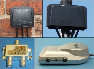
Amplifier basics including :
- Signal strength v signal quality
- Signal to noise ratio
- "Gain" of an amplifier
- Quoted noise & loss figures
- Variable gain (importance of)
Aerial splitters including :
- Splitter or amplifier ?
- Splitter losses
- Impedance matched system
- Power pass (for mast head amps)
- Internal splitters
- External splitters
- Typical uses of splitters
- More than one TV aerial on your house ?
- Splitting the signal from a satellite dish
- - And finally, avoid this crap…….
Mains aerial amplifiers including :
Terminators
Taps
Filters including 4G / LTE filtering
Diplexers including :
- Combining TV and FM / DAB
- Combining TV and satellite
- Combining modulated RF (e.g. CCTV)
- Combining signals from 2 TV aerials :
- - From 2 different transmitters
- - From the same transmitter
- Two signals in opposite directions !
- Diplexer built into a wall plate
Is my amplifier faulty ? (Incl : mains amps, mast head amps and Digilink IR return amps)
Amplifier Basics (including attenuators)
Sometimes known as “boosters”, there are more misconceptions about amplifiers than any other area in this trade. The crucial point to understand is the difference between signal strength and signal quality.
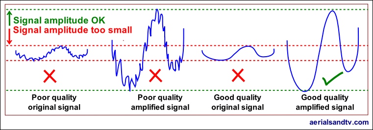
Assuming the downlead is OK (plus any wall plate), the only way to improve signal quality is at the aerial, either by changing its location/direction or by using a higher gain antenna. If one has a good quality signal but it is of small amplitude (hence the term amplifier) then an appropriate amp (particularly a mast head amp, and especially if the cable runs are long) can work wonders for picture quality. On the other hand if the signal is of poor quality and one adds an amplifier it will give no improvement.
All you will get is a large poor quality signal, as opposed to a small poor quality signal !
It’s not quite as simple as the above graphic shows because a low "signal to noise ratio" (or SNR) can also give digital picture break up or a low gain (snowy) picture on an analogue signal. Note how, in the graphic below, only a higher gain aerial has a positive effect on the SNR.
The noise referred to is background RF (Radio Frequency) noise which is around us all the time.
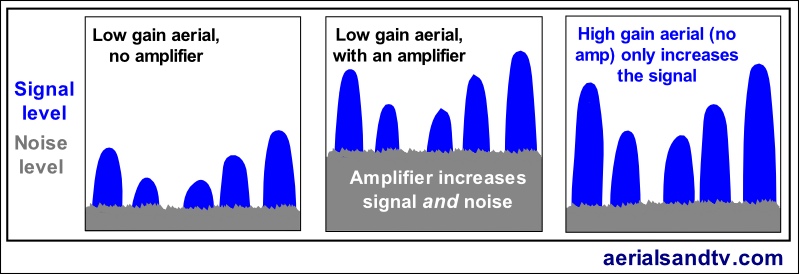
Above are typical displays from an RF spectrum analyser. Each blue waveform represents an RF transmission and this is the type of display you would get for a transmitter whose broadcast channels are “grouped”, e.g. Emley Moor. Digital MUXES on a spectrum analyser would be squarer and broader than the blue waveforms shown above (see Wright’s Aerials spectrum display of Emley Moor) but essentially it's the same for analogue or digital transmissions. NOTE analogue still exists, e.g. the modulated output from a CCTV camera.
Note that if an attenuator is used to reduce a signal level, or a splitter is used in the circuit (which has the same attenuating effect), the signal level and the noise level are both reduced. In actuality the S/N ratio can drop a little, but generally this is when the signal is smaller than recommended, and the further below this optimum level it is the greater will be the drop in the S/N ratio. Thus, assuming the signal is large enough in the first place, the S/N ratio (and the signal quality for that matter) will, effectively, remain the same no matter how many times a signal is split, assuming the splitters are of decent quality, obviously. Furthermore, if you have used a high gain aerial (e.g. to reduce co channel interference) and your signal level is now too high [which can give cross modulation interference] use of an attenuator will reduce the signal but still maintain the improved S/N ratio.
The amount of amplification given to the signal by an amp is called the gain and is measured in dB = decibels.
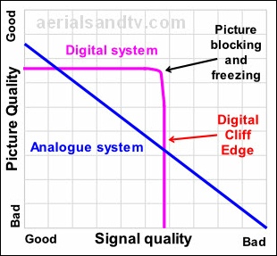
In the RF reception game plus 6dB is double, and minus 6dB (i.e. attenuation) is half. Although doubling the signal might sound like a lot, in most instances this amplification level (as opposed to gain at the aerial) would not make that much difference to the picture, unless, by pure fluke, it is the critical amount needed to attain the minimum necessary signal level, for digital this is 45 dBμV. With analogue signals (e.g. from an RF modulator) most tuners would not improve from a poor picture to a perfect one with just a 6dB increase in signal, but digital signals can sometimes be more critical. A small improvement can sometimes make all the difference, see adjacent graph illustrating the effect of the "Digital Cliff Edge".
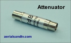
Too much signal can be just as bad as too little. A television tuner circuit has an inbuilt "AGC" (Automatic Gain Control) which will generally enable the receiver to operate satisfactorily with digital signals between 45 to 60 dBμV (equivalent for analogue signals is around one millivolt up to about ten millivolts = 60 to 80 dBμV). If the signal is below this range there is a risk of digital drop outs or, on analogue, a grainy picture. Excessive signal also gives digital drop outs (or patterning on an analogue picture) via cross-modulation interference in the tuner. Cross modulation is (in simple terms) the tuner being over driven. If one lives in a particularly strong signal area, even an unamplified signal may still be too great for the tuner to cope with. In these circumstances it is necessary to use an attenuator (sold here) to reduce the input level. Note that a 6db & a 12dB fixed value attenuator (CoAx or F conn) then gives the option of 6db or 12dB or 18dB total attenuation and is therefore an alternative to a variable attenuator. Furthermore the latter approach tells you how much attenuation you've actually used !
Unfortunately, very unfortunately, many digital boxes or TVs will report poor / low signal when the actual fault is excessive signal !
If you are unsure whether you have excessive signal try an attenuator (they’re not exactly expensive), or, if you have an amplifier in the system, try swapping it for a splitter, or bypass it but don’t just unplug it because then you’ll get no signal at all.
Lastly all amplification increases the chances of mobile interference, so only amplify if you really need to.....
To recap :
If adding an attenuator (or a splitter *) "improves" the signal that means your signal is too large. But if adding the attenuator makes the signal problem worse that indicates you have too little signal (excluding co-channel interference type issues).
* it amounts to the same thing, they both cause a reduction in the signal level.
Substituting an amplifier (particularly a higher gain amplifier) in the same test would give the opposite results, i.e. if the amplifier makes the problem worse you are likely to have too much signal, and vice verse.
Just like amplification, attenuation is also measured in dB, but it’s minus dB. It must be stressed that any amp in the system is just as likely to be overdriven as the TV tuner, thus if the input signal to the amp is excessive the attenuator must be utilised at this point, not just at the “setback”. That said, particularly for digital signals, there is more likely to be a problem in the TV’s tuner than any amplifier feeding it, so if you can’t get to the amp (say it’s on the roof) then try an attenuator at the set back. Incidentally attenuators are probably the most under used piece of diagnostic equipment, particularly considering they’re so cheap !
Unless you’re absolutely certain of the signal strength in your area I’d make sure that any amp you’re thinking of using is capable of accepting a reasonably large input signal so as to avoid cross modulation interference caused by overdriving the input stage. People whose aerials face the continent (e.g. Rowridge ) can often benefit from using an attenuator if (in certain weather conditions) they get excessive signal due to “lift” conditions and co-channel interference (CCI) from transmitters abroad. It must be emphasised that to have an effect on CCI (as opposed to excessive signal) the attenuator would normally be used in conjunction with a high gain / narrow beam width aerial.
One should also bear in mind that all amplifiers introduce additional "noise" to the signal and this should obviously be as little as possible. However, there is a trade off between amplifier power and noise. As a general rule the more powerful the amplifier (a launch amp for a big system being a good example) the higher the noise will be. But, if you think about it, a higher noise figure on a powerful amp is less important anyway because the total signal is so large.
A 100 dBμV signal is not going to be as affected by an extra 3dB of noise as much as a 45 dBμV signal that a mast head amp might have to deal with be. Noise figures should be around 3dB (or less) for a mast head amp, 4dB for a mains type distribution amp, or 6dB for a launch amp.
Now I’m an aerial man, I don’t particularly like satellites (boring things, which also help Sky make money......), but Bill Wright has strong feelings on claimed LNB noise figures : "If ever there was an area of human communication in which obfuscation, chicanery, duplicity, deception and good old fashioned bare-faced lies are dominant, it is manufacturers’ LNB noise claims. It used to matter when LNBs had noise figures of 2 or 3dB, but 0.2dB is below measurement accuracy because there are so many variables. I’ve tried hard to prove that a 0.2 is better than a 0.6, and failed." So, unsurprisingly, we have a rerun (another one) of the aerial gain marketing saga. I would only add that if you’re bothered about noise on your satellite signal I’d have thought you’d be better off using a larger dish......
If the noise figures quoted by manufacturers are a can of worms, so are the quoted loss figures for diplexers etc. I have spoken to various manufacturers about the noise/attenuation figures quoted by them and their competitors and, basically, some cast very large degrees of doubt on some of the claims of some of the others. What I would say is I’ve done some crude comparisons in loss between different makes of diplexers which have different quoted attenuations, and I couldn’t actually find much difference between them ! When I tested some amps "back to back" (comparing signal to noise readings) I found most amps were pretty much on a par, though some did seem to have appreciably worse noise figures. Unsurprisingly we don’t stock any of the latter. I suspect amplifier noise figures are a rerun of the aerial gain saga........
Wherever possible an amp should have variable gain and generally speaking the gain control should be turned down as far as possible to achieve the desired results, doing this will help to minimise cross modulation and/or co-channel interference. There are two main types of variable gain control, front end (generally a variable attenuator on the input), and interstage, where the signal level is altered after initial amplification. The latter is preferable as it gives better noise figures at minimum gain settings. For this kind of problem our 4 way M/H amp is particularly well specified as it turns down to only 1dB. Also see should I fit a splitter or an amp ?
Finally all amplifiers (or splitters) should be "screened" to help eliminate interference etc.
It cannot be over emphasised that gain at the aerial is much more significant than any gain added by subsequent amplifiers. It is only at the aerial that the critical signal quality can be achieved, see this aerial report.
Mains amplifiers / distribution amps
Generally, in domestic installations, amplifiers (or "boosters") fall into two basic categories, mains amps (discussed here) and mast head amps (discussed in this article).
The most commonly fitted are mains powered amps with relatively low gain, which are sometimes (misleadingly) called "setback amps". These tend to be used when the signal needs splitting to feed more than one set.
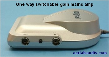
A typical gain figure for a mains powered distribution amp would be around 6dB but if the amp is (say) a 4 way one must add in the loss which would occur if a passive 4 way splitter were to be used in its place (see splitters). That loss would probably be around 8dB, so the effective "gain" would actually be 8dB plus 6dB, i.e. 12dB.
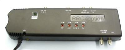
Some mains distribution amps have two inputs (one for UHF/TV and one for VHF/FM/DAB) which are combined together in an internal diplexer to give TV and/or FM/DAB out of all the outputs. However, not all amps, particularly older ones, accept DAB on the VHF/FM input, and, whilst on the subject, no (single input) masthead amps accept FM or DAB. So beware !
Lastly bear in mind that most mains amps do not have the benefit of variable gain and they have inferior noise figures to M/H types, so try not to put 2 in series as each amp will add some noise.
ATV stock 1, 3, 4, 6 and 8 way mains amps. All our amps are fully screened.
Many mains powered distribution amps give 12V “line power” out of the aerial input socket to power a mast head amp without the need for a separate PSU. Unfortunately it is not unknown for this to be at an insufficient current to reliably run some mast head amps and I’ve seen quoted figures as low as 25mA. Line power should be at least 50mA, and preferably 100mA. All of the 4, 6 and 8 way amplifiers we sell supply 100mA line power.
However, line power can have negative consequences.
Why ?
Basically most amps with line power have an auto switch off (for the 12V) which does this by detecting the presence of the short circuit which most aerials present. However if the circuit leaks even a very small current that can set up an electrolytic reaction in any joints, particularly those between dissimilar metals. This is made slightly worse if the cable isn’t copper copper, worse still by the presence of water, and far worse by sea water. Fumes from nearby chimneys can exacerbate it even further!
![Thus, if you live by the sea, particularly if you have a log periodic aerial*, we recommend not using an amp with line power. As an alternative try our one way mains amp (feeding a splitter if required) or its three way brother, or install an isolated wall plate (which will prevent the 12V going up the cable). [Link] NOTE : if there’s a mast head amp (being fed by the line power) in use below the aerial that eliminates the problem because no current should get through that, unless the mast head has a “cascade” facility, which hardly any do. * or, in the case of Log Periodics, the aerial itself. Remember for Logs the signal and current path is actually down the boom. So it travels all the way back, round the rear clamp and back up again. And all Logs have alloy booms and steel clamps = dissimilar metals. Thus, if you live by the sea, particularly if you have a log periodic aerial*, we recommend not using an amp with line power. As an alternative try our one way mains amp (feeding a splitter if required) or its three way brother, or install an isolated wall plate (which will prevent the 12V going up the cable). [Link] NOTE : if there’s a mast head amp (being fed by the line power) in use below the aerial that eliminates the problem because no current should get through that, unless the mast head has a “cascade” facility, which hardly any do. * or, in the case of Log Periodics, the aerial itself. Remember for Logs the signal and current path is actually down the boom. So it travels all the way back, round the rear clamp and back up again. And all Logs have alloy booms and steel clamps = dissimilar metals.](https://www.aerialsandtv.com/wp-content/uploads/2019/10/Line-power-leakage-can-cause-severe-corrosion-500W-L5.jpg)
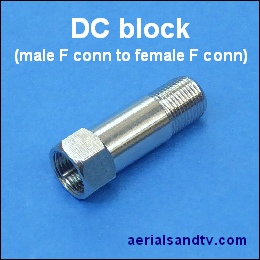
Thus, particularly if you live by the sea, and especially if you have a log periodic aerial*, we recommend not using an amp with line power. As an alternative try our one way mains amp (feeding a splitter if required) or its three way brother, or install an isolated wall plate or a DC block (sold here), either will prevent the 12V going up the cable).
NOTE : if there’s a mast head amp (being fed by the line power) in use below the aerial that eliminates the problem because no current should get through that, unless the mast head has a “cascade” facility, which hardly any do.
There is also a possibility of an electrical voltage being set up by "floating voltages" (very low current, they are not dangerous ! ) on a system, see this forum thread. Again isolated wall plates or DC blocks will alleviate the problem.
* or, in the case of Log Periodics, the aerial itself. Remember for Logs the signal and current path is actually down the boom. So it travels all the way back, round the rear clamp and back up again. And all Logs have alloy booms and steel clamps = dissimilar metals.
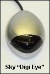
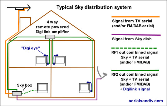
Some amps have an “IR (infra red) return path”. Many Sky boxes can be remote controlled from different rooms utilising “Digi Eyes” (next to the TVs) which pick up the remote commands and send them back down the CoAx cable [at 5 to 40MHz] to the RF2 output of the Sky box. An IR return path amp (or “Digi Link amp”) allows the passage of these remote control signals.
Note ! From August 2013 the boxes supplied by Sky do not have an RF2 output (don’t you just love Sky, not) so you’ll need to buy an IO Link adapter to restore the Digilink capability. Furthermore the Sky box will not supply enough current (via the I/O link) for a remote powered amp [if you’ve got one of the latter] and for these to work require an external power supply. This is all a PITA, but, to be fair, at least you can still get the Digilink working, you can’t (not easily) with Virgin or BT etc…..
Anyway, it’s important not to confuse the term "Sky compatible" amp.
1 - No amplifier can split/distribute a signal from a single LNB (on the dish) into a number of satellite tuners, this requires a Quattro LNB and a multiswitch.
2 - Any aerial amplifier can distribute the RF signal from a Sky box (i.e. the output from the RF2) to a number of TVs. However Digi Eyes will not work back through an amp (or, usually, any splitter) unless it has an IR return path (Digi Link).
3 - Only an IR compatible (Digi Link) amp will allow remote operation of the Sky box from a number of rooms. But if the use of remote eyes is not required then the IR return path capability of the amplifier is superfluous, see 2 above.
The graphic below shows a remote powered "digilink" amp, but maisn powered versions are also available (in fact we sell a 4 way and an 8 way).
Each aerial point in the illustrated example can receive the channel tuned in on the Sky box plus any transmission from the aerial(s). The Sky box can be remotely controlled via the Digi link eyes if required. Only three of the four outputs are in use in the system shown above.
If only one additional point (the solid green leads in the graphic) is required the connections to/from the Sky box would be the same but no amplifier would normally be required.
Unable to configure your system as in the graphic (possibly because the cable from your aerial only goes into the loft so you only have one cable running between your Sky box and the loft) ? See various layouts of setting up an RF modulator, including using a diplexer to add a second RF channel.
Also see :
Sky Digiboxes general information on the RF output/loop through.
Selecting a frequency for your RF modulated output.
Apart from co-channel interference issues the most common problems when setting up a Digi Link system are using isolated wall plates (we only sell non isolated / screened plates) and excessive signal from your aerial giving interference on the TVs connected to the extensions. Use of an attenuator at the aerial input to the Sky box will usually sort out the latter problem.
Launch / Power Amplifiers
There is another category of mains amplifiers called launch or power amplifiers. These are very high gain amplifiers and they can feed multi point systems with up to 100 (or more in some cases) outputs via splitters and/or taps. They usually come in 2 basic types, wideband (where the TV/DAB/FM signals are all pre-combined), or multi input, where there are separate inputs for the TV/DAB & FM signals. Unless effective pre-filtering is used we recommend the multi input type. The latter types often have separately adjustable gain for each input, the one we stock does anyway ! Another refinement is slope equalisation, where the higher TV frequencies are amplified more then the lower ones, this is to compensate for the differing attenuations through cable and splitters over the TV band. A typical launch amp has a maximum gain of 35dB, so its maximum output level (with a 70 dBμV input signal) would be about 105 dBμV. One can work out how many points one can feed by simple subtraction using the attenuation figures for the splitters and/or taps.
Larger distribution system utilising a power amp, taps and splitters
Note : you don't necessarily need an amp with a huge gain to provide a signal to a large number of points so long as the input signal is reasonable and the amp is capable of dealing with a large input level. Most amps cannot cope with a signal anywhere near this level (the signal overdrives the amp leading to signal distortion, usually cross modulation) though to be fair they wouldn't usually need to, why use an amp if your signal is high anyway ? On the other hand our 1 and 3 way mains amps are actually simplified launch amps and can therefore cope with signals up to 94 dBμV, thus the amplification of up to 18dB (on the 1 way) could give a very large output depending on the level of the input obviously.
We stock the previously mentioned amp but can also obtain larger Launch amps to order.
For actual input signal levels see this table.
Another use of launch amps is to preamplify signals which are to be transmitted down very long cable runs. As an example a 100m run of cable would attenuate the signal by up to 20dB.
Mast head amplifiers
The other type of amplifier is the so called Mast Head amp although this can be something of a misnomer as they are also be mounted on the wall, or even used in lofts, which can be convenient if no mains power socket is available there. These amps are powered by 12V sent back up the aerial cable by a "power supply unit" (PSU) which is plugged into one of the aerial points. These PSUs are often mistaken for amplifiers but in fact provide no amplification at all.
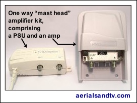
Furthermore if a PSU fails (or is omitted) the amplifier on the "mast head" (or in the loft) will be inoperative and no signal will reach the aerial point. Mast head amps are generally used in poor signal areas and they can give good results provided the signal is of good quality. They can also be used as distribution amps in conjunction with splitters. Installing the amp (or splitter) outside can often make the cable runs simpler / neater / quicker, but they can also be used in a loft where a lack of mains power precludes a mains amp. The major advantage of the mast head amp is the improvement in "signal to noise ratio" as it can be situated close to the aerial (the ideal distance is about 1m) and therefore it does not amplify any noise introduced to the signal by the cable. Mast heads are particularly effective where there is a long cable run from the aerial, and, it should be noted, even if the distance from the PSU to the amp is very long the amp will still work fine. This is because the attenuation in UHF signal level per metre is far higher than the fall off in the DC voltage (typically 1V per Km for decent quality cable) required to run the mast head amp. Thus all the mast heads we sell (even a 5V one, which we don't sell) should still work fine at well over 250m !
I am of the view that amps with variable gain capable of being decreased to a low level are more appropriate, and are more flexible in their application, than those with higher gain. All the M/H amps we sell have variable gain to overcome this problem, for instance the gain of the 4 way universal varies from 1 to 16dB. If you really feel you need more than 16dB of gain I think you want to be looking at your aerial, for example can you use a grouped one ?
It should be noted that if the PSU is required to supply its voltage back through a surface plate the latter must be non isolated, because the capacitors in the isolated variety will not pass DC. Whilst on the subject of wall plates, be careful which type you fit we do not recommend budget non-screened types, we only sell screened non isolated plates.
As with amps and splitters the PSU should be of the screened type to minimise interference. Most M/H amps seem to have superior noise figures to mains types though I’m unsure why this is. Maybe it’s just because noise is more significant with a small signal (and this is what is expected with a M/H amp) so more priority is given to this parameter during the design stage(s). Note that the vast majority of M/H amps only amplify UHF, not VHF and UHF, as most of the mains ones do. If both VHF (FM/DAB) and UHF (TV) are required I recommend diplexing the FM/DAB signal in after the mast head amp, it’s highly unlikely you will significantly degrade your VHF signal via a splitter, even an 8 way. In fact amplifying FM in particular can sometimes give worse results.
Finally, grouped mast head amplifiers did once exist. If you aren’t getting all the channels for some unknown reason, check the M/H amp isn’t a grouped one !
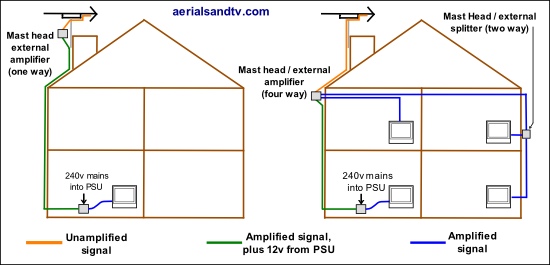
Installations using Mast Head amplifier(s).
The picture above shows typical installations involving mast head (i.e. external) amplifiers.
On the left we have the simplest installation of a one way mast head amp feeding one TV point, note how the distance that the weak unamplified signal has to travel is minimised, ideally about one metre.
On the right is an installation utilising a four way mast head / external amp, though in this case only three outputs are in use, thus a spare is still available if ever required. I have added an external splitter on one of the outputs simply to show that this is possible, but an additional benefit is a neater install. In fact, if it results in more elegant cable runs, and less use of cable, it is perfectly acceptable to use a one way amp near the aerial and then run into one or more splitters (external or internal) to feed the various points.
Note how the Power Supply (PSU) is located inside the house. It is usually placed between an aerial output and the set it feeds, thus explaining why it is often mistaken for a “booster”. The actual amplifier has a weatherproof enclosure and is usually (but not always, they're sometimes in the loft) placed outside, often strapped to the aerial pole. The nearer it is to the aerial (1m ideally) the most positive effect it will have on the signal to noise ratio. That said even 3 or 4 metres is far preferable to a typical cable run of 15m, or more.
Care should be taken when installing any PSU that the output is not shorted out, e.g. straight into any aerial. This can damage the unit. particularly if it doesn’t have short circuit protection.
A four way mast head amp works in exactly the same way but with the PSU placed on the most convenient output (most amps have the facility for this, though not all).
Terminators
Let’s get one thing clear straight away.
When we’re talking terminators we’re talking what to do with any unused outputs on an amp or splitter, it’s got nothing to do with an unfeasibly large Austro American actor.
Any aerial system should be impedance matched and therefore amps/splitters are intended to work into a 75 Ohm load. On the other hand most amps/splitters are designed to accommodate a proportion of the outputs being unused without significant effects. Terminators are designed to put a 75 Ohm load on an unused output of an amplifier, splitter or tap.
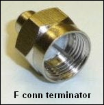
There are three schools of thought about whether terminators are necessary :
Some say terminators are hardly ever required in domestic jobs.
Some say they are advisable if half (or more) of an amplifier or splitter’s outputs are unused.
Some say all unused outputs should be terminated.
Terminator always used to be required for the “Full Output” of a mains distribution amp (if it’s unused obviously ! ).
Back in May 2009 I did some simple tests and this was certainly confirmed back then because omitting the terminator from the "full output" meant the amp was actually giving out less (on average) than the input, i.e. not terminating the full output effectively “lost” 6dB of gain ! A splitter on the Full Output had the same effect as a terminator, even if the splitter’s legs were unterminated. Plugging in an unterminated 30m length of cable to the Full Output resulted in the amp “only” losing 4 to 5dBdB, i.e. it had a slight loading effect.
However......
When I tested our latest model of mains amp (the one we started selling in Oct 23) I found no significant difference in gain with or without the terminator in the "full output" ! The manufacturers also state that "a terminator is no longer necessary on the full output" of this particular amp.
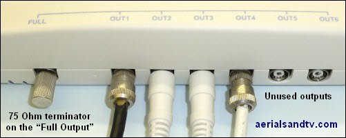
The situation has always been rather different with the unused standard outputs of a mains amp, or indeed the outputs of a mast head amp, or a splitter. In my tests the average difference (across all 11 test frequencies) between the worst case scenario (i.e. only one output of a device being used) and all being used or terminated was generally less than 1 dB. The standard outputs of mains distribution amps were least affected by lack of termination. That said, some of the frequencies had bigger differences than others.
In these (admittedly simple) tests, use of terminators had an inconsistent effect on the losses of different models of splitter, sometimes increasing it, sometimes decreasing it, but always by a relatively small amount. On the other hand they marginally increased the gain of all the amplifiers.
Terminators should not normally be fitted to unused outputs of IR return path (Digi Link) amps.
Conclusion : If a distribution amp has a Full Output (not all do) and it is unused it should definitely be terminated. In other cases, for domestic systems, terminators are not that important, though they do have an effect on the margin.

