How to attach / wire up plugs, aerials and wall plates
Subject list:
- How to strip CoAx cable
- How to attach a CoAx connector plug
- How to attach a Right Angle CoAx plug
- How to attach an F connector plug
- How to wire up a (screened) wall plate
- How to wire up a (screened) diplexed/triplexed wall plate
- Repairing a budget unscreened wallplate
- How to wire up an aerial with a dipole PCB
- How to wire up an aerial without a dipole PCB
- - also see fitting a cradle to an aerial
- How to assemble an FM clamp
- How to wire up a Log36
- Log Periodic aerials : tilt them up at the front end!
- - including waterproofing junction boxes
- How (not) to put an aerial together
How To Strip CoAx Cable
You can buy cable stripping tools, but I have to say most aerial installers don’t use them, which must tell its own story. I’m unconvinced by them myself, and, along with most installers, prefer to use the method below.
Two things to bear in mind, the sharper the knife the better, if it’s sufficiently sharp then just touching the outside of curved cable will be enough to split it (unless it’s cold......). Secondly, try to ensure as little of the screening braiding is removed as possible.
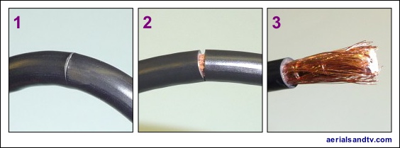
1 - Using a sharp knife, cut lightly all the way round into the cable’s outer insulation, but not all the way through to the braiding below.
2 - Bend the cable, which will split open the insulation without cutting through any of the screening braids, assuming the weather isn’t too cold........
3 - Pull off the outer insulation you’ve just cut through.
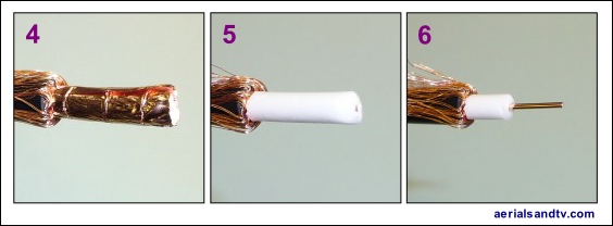
4 - Fold the screening braids back over the cable’s insulation. Note how decent cable has a foil, preferably a copper foil.
5 - Remove the foil, assuming you haven’t got crap cable, in which case you won’t have a foil..... Note, the foil can cut your finger!
6 - Cut through the insulator and remove it to expose the centre conductor.
Wiring up a CoAx plug (also see stripping CoAx - above)

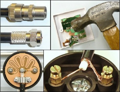
When attaching CoAx plugs it is always worthwhile slightly kinking the centre core of the cable (before you assemble the plug) so as to maximise the chances of good contact between it and the plugs centre pin. Some people recommend soldering this connection but I’m not sure it’s really necessary or advisable, it’s probably more likely that you will just melt/deform the plastic centre spacer rather than adequately solder the centre core ! A better idea than soldering is to lightly crimp (to crimp, posh word meaning to squash) the centre core of the Co-Ax plug at the bottom end near the insulator.
It is not unknown to get a loose fit between the CoAx plug and the socket because the tolerance required to get it snug is extremely fine. A few minutes with some verniers revealed that a difference of just 0.05mm was enough for a reasonable fit to become a loose one, and that’s half the diameter of the average human hair ! It should be noted that it isn’t the fit of the outer barrel which is primarily responsible for a tight or loose plug, it’s usually the fit of the centre core into its female equivalent on the socket. So the solution to a loose plug is reasonably straightforward, slightly crimp the plug’s centre core (this is good practice anyway, see above), and/or the female equivalent on the socket. Only in exceptional circumstances is it necessary to gently squeeze the CoAx plug barrel [or the socket it’s going into] so it’s slightly oval.
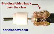
Some people recommend splaying the screening strands back over the “claw” (see picture), as opposed to folding them back over the insulation and under the claw, as above. Theoretically this puts the cable’s screening directly in contact with the body of the plug. On the other hand it’s messier, and personally I can’t remember ever having a problem with the “conventional way”. So you pay your money, and then you make your own mind up.
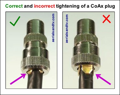
Do not over tighten a CoAxial plug if you want to maximise the strength of the claw, i.e. make it harder to pull off !
The LH plug (in the adjoining picture) is tightened to the optimum for the collar to hold the jaws onto the cable. Do not screw up the collar as far as the RH plug because the jaws on the claw are then free to bend outwards.
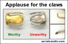
Applause For The Claws, well the one on the left anyway.....
Ensure the Co Axial connector’s claws are actually shaped to grip the cable, many aren’t, the ones we sell are.
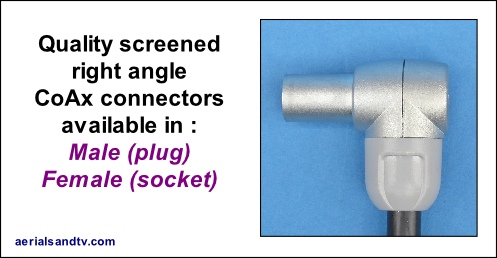
How to attach a right angle CoAx plug
We now sell a different type of right angle CoAx plug / socket, and wiring up those is self explanatory. However, we have left these instructions on for reference.
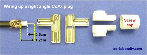
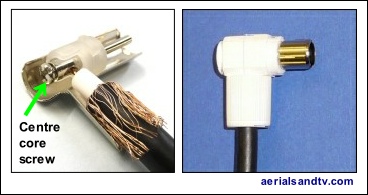
Before you attach the plug, thread the cable through the screw cap ! After trimming back the cable (as above) insert the centre core into the screw clamp and tighten to make good contact, though not too much that you cut the end of the wire off, or shear the screw...... Then assemble both sides of the metal plug and the top and bottom plastic cover, finally clamp it all together by screwing on the cap.
Wiring up an F connector

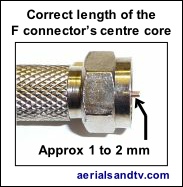
The F connector should be screwed onto the cable until 1 to 2 mm of the centre core protrudes from the top of the F connector. Note that the connector should be a fairly tight fit on the cable, that’s what stops it pulling off ! If the correct screw on F is attached to the cable (and there are different sizes of each, our F connectors are correct for our cable), then they won’t come off, not unless someone tries to use the cable to abseil down the house......
Also see crimp on v screw on F connectors.
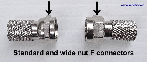
Note our F connectors with the "wide nut" are easier to use.
Wiring up an aerial with a dipole PCB
The PCB would usually be a balun but not always (particularly with FM aerials).
Use this article in conjunction with stripping CoAx cable.
Why I prefer saddle and clamp connections (as below) over F connectors on Yagi aerials.
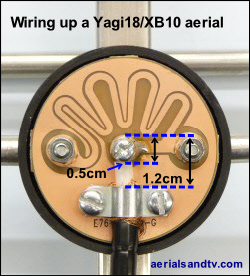
The adjoining picture is one of our Yagi 10/18s, but the dipole connector in our XB10/16s and DAB aerials are very similar.
Remove the cap from the dipole and first push the cable through the hole. Now, and only now, trim back the cable as in the diagram noting that the outer insulation of the cable (which gives the cable its 6.5mm diameter) should be under the braid clamp with the screening folded back over the aforementioned outer cable insulation (but under the braid clamp). Ideally try to fold the outer braiding under the cable so as to maximise contact with the pad on the balun PCB. Tighten all screws firmly but not too far that they shear off the centre core or excessively crush the cable. Replace cap, and then tape the cable to the aerial such that is is in a downward direction where it exits the dipole cap, so as to minimise the possibility of water seeping in.
If the aerial is centre mounted, as all large aerials should be, most manufacturers recommend routing the cable back down the reflector and then onto the pole (because that’s the position it’s in when tested for benchmarking), but we found no difference in signal level when routing the cable forward. And it looks much better......
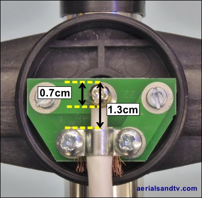
Not all PCBs are baluns and this is particularly the case for many FM aerials where it is often difficult to fit a balun in the dipole connector box. In these cases the PCB is simply used as a method of connecting the cable to the dipole(s).
The adjoining picture is of the dipole connector in our FM aerials.
NOTE ! : The cap of the Half Wave dipole in particular is a very tight fit to make it as weatherproof as possible. Thus we strongly recommend warming it in hot water before fitting it so as to minimise the possibility of it splitting.
Wiring up an aerial without a dipole PCB
Use this article in conjunction with stripping CoAx cable.
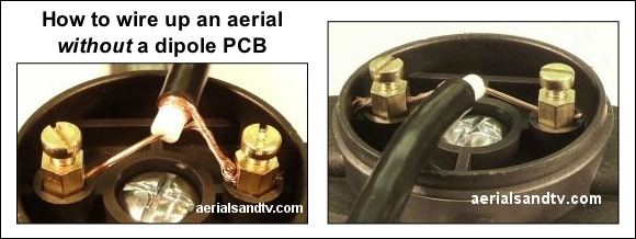
Connect up the aerial as in the pictures, having fed the unstripped cable through the hole in the cap, and then stripped it...... Generally it doesn’t matter which wire goes to which terminal, but some say, in the case of a Half Wave dipole type aerial, that the element connected to the centre core should go at the top, my advice is to experiment. After wiring up replace the cap, and then tape the cable to the aerial such that is is in a downward direction where it exits said cap, so as to minimise the possibility of water seeping in.
Why I prefer saddle and clamp connections (as above) over F connectors on Yagi aerials.
Assembling an FM clamp
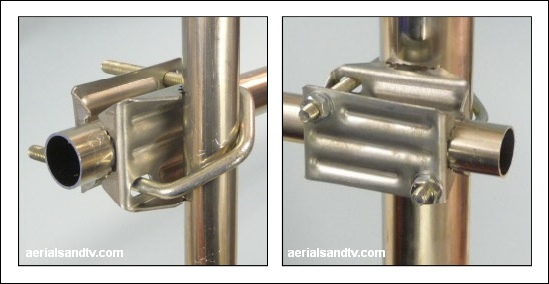
The FM Half Wave dipole and FM Folded Dipole both have 1in booms and generally come with the above clamp, which fits all poles between 1in and 2in. It will be noted how the aerial’s mounting boom can be rotated to change polarity, vertical (the default for FM and DAB), horizontal or even diagonal !
The picture on the left shows the aerial mounted on a 1in diameter loft kit, the right hand picture showing it on a 2in pole. It must be admitted it’s a tight fit on the latter, but it does fit, as the above picture proves !
How to wire up a Log36 TV aerial
Note : the self amalgamating tape is not required for loft installs !
The pictures below are fairly self explanatory, but also see how to strip CoAx cable and how to attach an F connector.
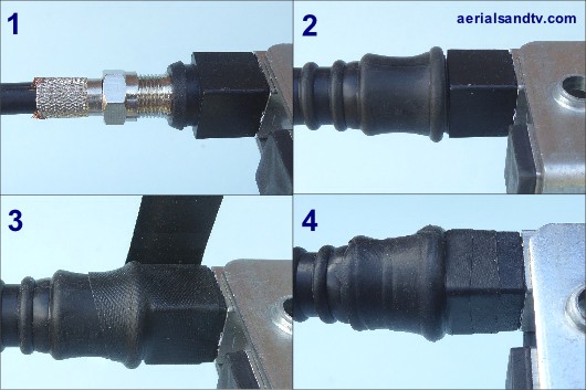
In Jun 2018 the self wired Log36 was discontinued, a retrograde step in my view because I don’t fully trust F connected aerials* because the “boots” are not 100% waterproof. Thus we supply 1ft of self amalgamating tape with our Log36s (excluding loft install kits), though 6” of self amalg is actually more than enough. We supply 1ft so you’ve got some spare if you make a bollox of using it the first time or you need to rewire the aerial for some reason. In either case be very careful removing the old self amalg, do not damage the boot beneath. Anyway, the first job is to cut off 6in of self amalg ! When wrapping the self amalg stretch it to about half its width and overlap it by about half a width.
NOTE 1 : We recommend that when installing the Log36, or any Log Periodic aerial, the front end is tilted a few degrees up.
NOTE 2 : Hard wired aerials do not require self amalgamating tape, provided the cable, where it exits the balun cover, is angled downwards.
* if we get a choice we always sell hard wired aerials, e.g. the Yagi18K, which is the next aerial up, (gain wise) to the Log36.
