Decibels, μV and dBμV
Subject list :
- Brief explanation of the Decibel
incl definition of dBμVs and dBmV
- dB as a ratio
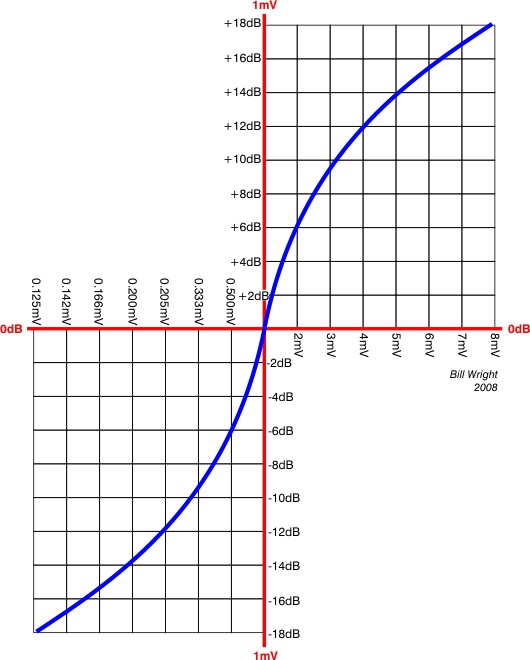
incl graphs of dB to ratio and dB to 1 mV
Before we go any further we must clarify the difference between decibels in terms of power and decibels in terms of level. Just to hammer the point home :
Decibels level wise (e.g. Volts) v Decibels power wise (e.g. Watts = Volts x Amps)
When it comes to dB the two differ by a factor of two. For level a doubling equates to 6 dB, whereas for power doubling equates to 3 dB. It’s the difference between the power (Watts) applied to the transmission aerial and the signal level (Volts) resulting across a 75 Ohm aerial. In the aerial game we’re interested in signal level, specifically at the input to the TV tuner.
All dB figures quoted on this site are for signal level.
The Decibel (or dB for short) is a much misunderstood unit, it is simply a ratio. For an amplifier (or splitter) it is the ratio between the input signal level and the output signal level. In the case of aerial gain it is (or should be) measured in dBd, that is gain as compared to (i.e. the ratio to) just the dipole on its own. Some aerial manufacturers quote dBi, which is gain relative to a theoretical isotropic source. I’m not really sure what the latter is, and, to be perfectly frank, I’m not that bothered either, because aerial gain in the real world should be measured in dBd anyway. I object to manufacturers trying to make their aerials seem higher gain than they really are by quoting dBi, and hoping the customers don’t know the difference.
To convert dBi to dBd deduct 2.15.
In fact manufacturers shouldn’t just quote peak gain anyway (whether in dBi or dBd) because it’s potentially misleading....
Either way 0dBd or 0dBi does not mean that no signal would be received by the aerial. 0dBd just means that the aerial only picks up the same amount of signal as the dipole would on its own (i.e. with no reflector or any directors), 0dBi means it’s 2.15dB down.
The dB is a logarithmic scale and this can be very helpful helpful in the aerial game because big differences in signal can be worked with relatively simply. This is achieved by using dBμVs instead of mVs :
dBμV = dB relative to one microvolt.
Since 0dB means no increase or decrease, then 0dBμV = 1μV
that is to say : 0dB x 1μV
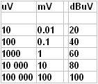
Other levels are shown in the accompanying table. By using dBμV simple addition / subtraction can be utilised to calculate signal levels throughout a system, including, crucially, at each TV input.

Some installers who specialise in system work work in dBmV where : 0dBmV = 1mV
Therefore : 0dBmV = 60dBμV and (in the other direction) 0dBμV = - 60dBmV
Examples : 20dBmV = 80dBμV - 10dBmV = 50dBμV - 20dBmV = 40dBμV
Worked Examples of System Planning
These examples assume good signal quality.
The preferred range at the TV input is 45 to 60dBμV for digital (60 to 80dBμV for analogue) for digital TV aiming for 50 to 55dBμV makes sense.
For FM some sources quote 60 to 75dBμV, and for DAB 40 to 70dBμV. However, most FM tuners will work perfectly well (in stereo) on signals down to 50dBμV and some down to 40dBμV or even less. Arguably one should aim for 55dBμV (FM) and 45dBμV (DAB).
As an example, for digital TV, if one has 65dBμV at the aerial (a strong signal area) and one loses 3dB due to the cable, then utilises a 6 way splitter (loss 10dB) one can easily calculate the output by simple subtraction.
Thus : 65 - 3 - 10 = 52dBμV, i.e. it should work fine !
Amplified systems work in the same way, e.g. input signal 45dBμV (weakish signal area), then gain through the amplifier 20dB, then the loss through cable 3dB, then through a 4 way splitter (loss 8dB).
Thus : 45 + 20 - 3 - 8 = 54dBμV, i.e. it should work fine !
Also see this example of system planning using taps and splitters.
dB as a Ratio
When it come to amplifiers, or attenuators, the ratio is the output compared to the input.
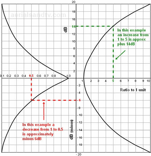
Examples (shown on the graph below) could be :
A 14dB increase will give an output level of 5 from an input level of 1.
Thus, in the case of an aerial amplifier, a 1mV input will give a 5mV output.
Minus 6dB ( = attenuation) makes the output level half of the input.
So, if using a 6dB attenuator, a 1mV input would result in a 0.5mV (500μV) output.


