Basic aerial facts and theory
Subjects are list :
Basic Aerial Facts including :
- “Set Top” Aerials
- Omni directional aerials
- Aerial Positioning / RF Dead Spots
- Signal Meters TV signal indicators
Basic Aerial Theory : Yagi type incl:
- Components of a Yagi aerial
- Definition of aerial “gain”
- Baluns
Also see Log Periodic aerials
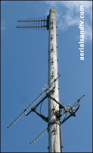
Basic aerial facts
The aerial and its downlead (see cable) are taken for granted by almost everyone, but they are just as important as the TV and in fact (electronically speaking) are actually part of it. Many people will happily spend hundreds of pounds on their television but are, apparently, unwilling to spend any more than is absolutely necessary on their aerial installation. This is an important point because the difference in gain between a cheap "contract" aerial (or DIY wideband aerial) and, say, a Yagi18 of the same group, can sometimes be quite small, but it will make some difference, and that difference (particularly with digital signals, see “Digital cliff edge") could make all the difference. More certainly there are big differences in build quality between many of the aerials available on the market. Remember that a decent aerial installation should last 20 to 30 years or more, and at the end of the day what’s the cost of a good quality aerial install compared to the cost of the average TV, or your sanity when your Digital picture starts freezing !
We would normally only recommend fitting TV aerials in lofts in decent signal areas. That said, since the Digital Switchover Over when the power was increased many more people find a loft aerial is sufficient, see page on loft aerials.
You need to be an even stronger signal area to get a reliable signal from an indoor / “Set Top” aerial but post switchover many people find one can give acceptable results, see page on set top aerials.
Finally, Omnidirectional TV aerials are even less likely to be effective than "set tops", in fact Omnis actually have negative gain. If you get ever get good results from one you’re probably in an excellent signal area, a coat hanger would probably work as well ! See Omnidirectional TV aerials.

Aerial positioning can sometimes be of critical importance, particularly when anything is close to the aerial, e.g. the chimney. Bear in mind that at UHF frequencies the wavelengths are between 14” and 25” so moving an antenna a few feet (vertically or laterally) can sometimes make a big difference to signal strength or multi path reception. Aerial positioning can be particularly important if trees or high buildings are near to the aerials reception path from the transmitter. Furthermore, although they are rare RF (radio frequency) “dead spots” do exist, that is to say a fall off in signal level without anything obstructing the ’line of sight’ to the transmitter. They are caused by the reflected (out of phase) RF waves interfering with each other. “Dead spots” tend to be more common in hilly or built up areas but reflections from the ground can give the same effect. Use of a “High Gain” aerial can help but what is really required is to resite the antenna. Unfortunately this is a time consuming business and there is no guarantee it will be effective. As an aside, when it comes to aerial positioning a DIY installation can sometimes be more effective than a professional one. Why ? Well most installers haven’t got time to experiment placing the aerial all over the house, and if they did have time they’d (quite rightly) expect to get paid for it, whether it worked or not. The same principle apples to experimenting with the reception on different transmitters. On the other hand a DIYer is usually prepared to spend his own time on the chance it might work. For more information see aerial positioning tests page.
Cheap signal level meters are not generally worthwhile, except possibly for boaters or caravanners, though to be frank, in my experience, I’m not even convinced they’re that much use for that ! £30 meters are of questionable accuracy, often only work in huge 10 or 20 dB increments and, even more significantly, they’re not frequency dependent, i.e. they only give one reading for all the received transmissions. The only meters I’d recommend would cost about £300, or more. You’re best off aligning your aerial using a map, that will usually give the best signal. After that try your TV’s signal level indicator, though even these are not always to be relied on. Many TVs’ signal level readings really aren’t that accurate and can even report low signal (or no signal) when in fact there’s too much signal ! Interestingly I have found the "signal quality" readings more accurate than those for "signal level". However, at the end of the day, the only thing that really counts is do you get all the channels you should and do they “break up” ? So use that as the best guide as to optimum aerial alignment (or amplifier gain setting, or even removal of the amp). Also try experimenting with fitting an attenuator (a cheap and VERY much underrated piece of diagnostic equipment) and remember that different TV’s tuners can vary in their performance……
Note : 4G and 5G transmissions can make cheap signal level meters worthless because the 4G signals are within the frequency band which the cheapo meter is looking for. It may report large signals in a particular direction but that might just be a 4G mobile phone mast ! You can get round this by using a filter between the aerial and the meter (we recommend a CH57 / K+ group filter), though meters sold after summer 2013 may have built in filters, check with your supplier.
It must be admitted that fault finding on analogue signal was far easier, but that’s gone......
Bearings worked out on a map or using the Digital UK postcode predictor are a good place to start but remember RF is a black art, it’s not a science....
It cannot be over stressed that gain at the aerial is much more important than any gain added by subsequent amplifiers. It is only at the aerial that the critical signal quality can be achieved.
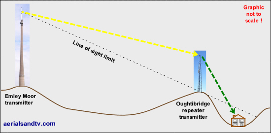
Lastly, always remember that ”line of sight” is (almost) everything. Which transmitter have you got the clearest view of ? This is far more important than which is the nearest......
Basic aerial theory - Yagi type
Historically the vast majority of aerials have been Yagis* which basically work by "focusing" the RF (Radio Frequency) waves coming towards them on to the dipole. The electro magnetic RF waves induce electrical currents into the elements of the aerial and it is this which becomes the signal at the dipole. The latter is the driven element which actually "collects" the signal. All the other elements either act to "focus" the required RF (the directors and the reflector) or prevent unwanted RF reaching the dipole (the reflector). Note that neither the directors nor the dipole have to be in electrical contact with the boom.
Yagi aerials, particularly high gain types, are very directional and it was this property which the Germans used when they were attempting to detect Resistance radio operators in WW2. Operatives would be monitoring for any transmissions and by utilising the directivity of the antennas they could plot which direction they were coming from. If two or three teams were doing this simultaneously the plots could be drawn on a map and the transmitter was at intersection of the lines. No wonder the radio operators had such a short life expectancy, very brave, I wouldn’t have done it, no chance.
* Log Periodics are becoming more popular these days.
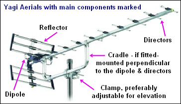
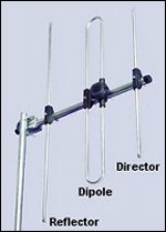
Above is a 13 element (see element count) TV aerial and 3 element DAB aerial, illustrating the main components found on Yagi type aerials.
Note the use of a cradle on the TV aerial which it is good practice to use for all “high gain” aerials (particularly high windload aerials) due to their higher wind loading. Mounting cradles strengthen the aerial and also reduce the twisting forces exerted on the pole and clamp. End mounting aerials can exert a very high torque on the aerial pole when the wind blows. On the other hand Log Periodic aerials should always be end mounted, though our tests on this were inconclusive to put it mildly. On a related point if any aerial is fitted with a cradle this should always be fitted perpendicular to the dipole so as not to interfere with the tuning of the directors. Similarly the pole can also interfere with an aerial's tuning, particularly if it is vertically polarised.
For any aerial the tuning of the elements is critical. This is a highly specialised job and it is fundamental to the performance of the antenna. If a Yagi aerial is designed to work over a large section of the band (a “Wideband”) it cannot be tuned precisely and therefore its gain and directivity will be lower. You have to remember that Yagis were originally designed as single frequency aerials. Thus if you really need a high gain aerial and are able to use a grouped antenna on your transmitter, a grouped aerial is always preferable. This is particularly true in the case of the A group, but also (to a lesser extent) K group and B group transmitters. Having said that, most people don’t need a high gain aerial !
Before we go any further we must remind ourselves that having an amplifier in an aerial is not the same thing at all as aerial gain !
As more elements are added to a Yagi aerial (provided they are “tuned” correctly) the acceptance angle narrows and the amount of signal “collected” (the ”gain” ) increases. Gain is measured in decibels or dB [this is a logarithmic scale] and for aerials it should be measured as dBd, which is the increase in signal received from an antenna compared to that which would be measured from just the dipole on its own. Note that 0dBd does not mean that zero signal would be received by the aerial, it just means that the aerial only picks up the same amount of signal as the dipole would on its own, i.e. with no reflector or any directors. In fact the vast majority of FM and DAB aerials are just dipoles (which therefore only have a gain of 0dBd) yet they work fine in most cases. On the other hand TV has rather more stringent requirements, a TV aerial of only 0dBd would need a very strong signal to work OK.
Always remember that there is more than one way to measure gain, e.g. dBi and dBd, the latter being the more honest parameter. To convert dBi to dBd deduct 2.15 from the dBi figure.
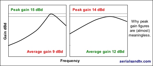
Gain is not everything but it is the simplest most objective measure of the efficiency of the aerial, though you should always be careful when comparing the quoted peak gains of aerials.
Decent Yagi aerials have a "balun" in the dipole which is usually a small PCB built into the dipole assembly and it’s designed to maximise the signal by impedance matching the dipole to the cable, hence the name from the term balanced unbalanced. Baluns are reputed to help eliminate impulse interference which can be one of the causes of intermittent blocking or pixellation on digital signals. Some say the best aerials for eliminating impulse interference are Log Periodics, because they theoretically short it out to earth (assuming the aerial is bolted to the brickwork of the house), but this is not a universally accepted theory. Personally, wherever possible, I think it far better to trace and eliminate the impulse interference at source. Note that neither half wave open dipoles nor Log Periodic aerials need a balun because they have a natural impedance of 75 Ohms across the full band (Log’s individual elements are, in effect, half wave dipoles).
Also see : why does my aerial read short circuit ? plus aerial balun tests and wiring up an aerial.
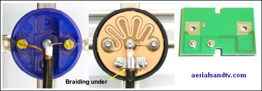
The dipole on the left has no balun, the one in the middle has got one. The PCB on the right is an alternative type of balun shown from the underside.
Incidentally, when wiring up an aerial with a balun I’d try to maximise contact (of the cable’s outer braid) with the metallic pad on the balun PCB [below the cable], as opposed to the screening clamp, because the screws of the latter are not always in good electrical contact with the PCB.

