ATV's aerial positioning tests

All these tests are investigating the effect of positioning on an aerial installation’s gain (using the definition the amount of signal it collects) and they prove conclusively that the position of an aerial can be vital to its effectiveness. The tests on this page are all outside but aerial positioning can be even more critical in a loft, and in a loft the optimum position can even vary for different aerials ! I say can be, rather than always, because the adage that RF (radio frequency) is a black art it’s not a science, is demonstrated time and time again in this section. I think Bill Wright’s comment about RF is apposite :
“If you could see RF, you’d see some incredible and totally unexpected things”.
Consequently none of the results published here can be regarded as definitive as every installation is different. There are so many variables e.g. the frequencies / wavelengths involved, the transmission path to the aerial, the distance to the wall / roof / trees / next door’s house etc etc. All of these factors can result in more reflection, diffraction or cross polarisation of the signal, also see Fresnel zones.
What can be established is the basic principle that an aerial will almost always operate most effectively high up and in free space, i.e far from any other objects which affect RF.
Notes. All test results are averages of at least two readings. The figures are for peak reading for analogue channels or integrated channel power (over the 8MHz bandwidth) for the digital channels. This is purely of academic interest because we are only interested in the difference between the readings in any of the tests. No account is taken of possible multipath effects because there is no objective measure of that, and it would take too long to do it anyway !
The Tests :
- Reflectorless Aerials
- Polarity of Obstruction(s)
- Incorrectly Fitted Cradle
- Aerial Height Tests (incl proximity to the roof ridge)
- Aerial Lateral Position Tests
- Aerial Separation Tests (how far apart to mount aerials)
- Use of a cradle with a Log periodic aerial
- Signal loss with (only) half an aerial
- Loft Tests
- Directors not unfolded
The Black Art Of RF Reception…….. And again…….
Reflectorless aerials
One often sees aerials about without their reflectors, especially Contract types (where the installer hasn’t bent over the tang on the plate which is supposed to prevent it falling out) or Bacofoil aerials where the reflector elements have fallen off.… But how much signal is it actually losing ?
Whilst up at our test site I had a play about with a Yagi18B on Emley with its reflector in various stages of dismemberment. Crude tests I admit, but interesting.......
Note that these tests are purely for forward gain, they do not test attenuation of signals from the rear. I did start off trying to check the latter but it quickly became apparent that the readings were inconsistent (to put it mildly) and therefore that test was of no practical value.
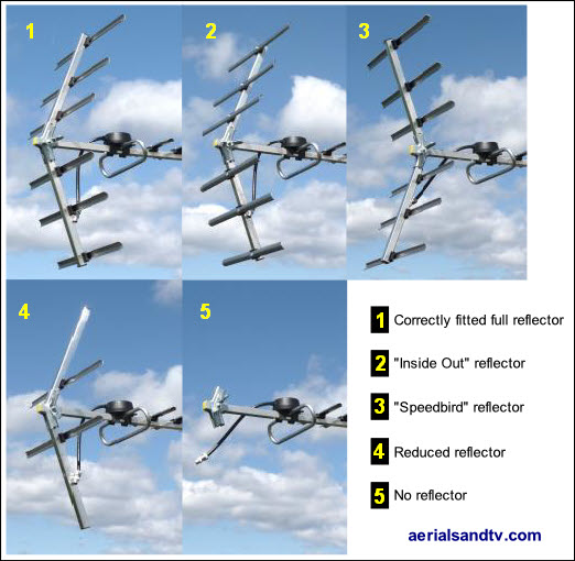
1 - I started out with a correctly fitted full reflector.
2 - First I put on the reflectors "inside out", and there was no significant difference.
3 - Next, I deliberately fitted the reflectors angled the wrong way (Speedbird style.....) and the aerial lost 1.4dB.
4 - Then I removed 4 (of the 6) reflector elements, interestingly the aerial only lost 0.8dB.
5 - Finally I found that no reflector at all knocked 3dB (average) off the gain.
The test results prove the lack of a reflector has a significant effect on the gain, though in a strong signal area a reflectorless aerial may still well work OK. On the other hand, if the antenna has a reflector but it’s at the wrong distance from the dipole (such that reflected waves are 180 degrees out of phase) it would actually have more of a negative effect than not being there at all !
Effect on aerial gain from an incorrectly installed cradle
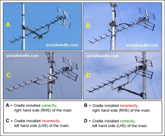
In this test we deliberately installed the aerials cradle incorrectly, that is to say parallel with the dipole/directors as opposed to perpendicular to them, see the pictures below. As mentioned on Aerial Arrays, many years ago we deliberately mis-installed the cradle on our Belmot XB10A (by placing the cradle parallel with the dipole/directors) and we were amazed at just how much worse the picture was. We really shouldn’t have been surprised, if you think about it the whole tuning of the antenna is changed by such a bodge. So the purpose of this experiment was to put some sort of figure on just how much signal one can lose by placing the cradle in the wrong position. The actual loss (in dBs) varied according to the frequencies involved, which is what one would expect. It must be stressed that the level of loss would probably vary depending on the model of aerial but it’s a fairly safe bet that it would always be significant. That said, if you’re in a strong signal area anyway then your picture would still be fine. The only problem you’d have is any passing aerial installers laughing at your antenna. Actually your errant install may not generate much amusement, because, in my experience, many aerial installers don’t actually know what best practice should be anyway…..
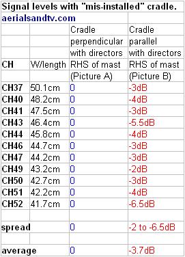
An average signal loss of 3.7dB is very significant. In fact to achieve a increase in gain of that amount from an aerial takes a lot of effort. As an example a Yagi 18B only averages + 3.1dB gain over a Log36.
Just out of interest we then positioned the aerial on the other side of the mast (picture C) and there was an additional signal loss of about 2dB (on average), just for moving an aerial about 14” to one side (also see lateral positioning tests). CH41 (which was analogue C4 off Emley) was particularly badly affected, a total of 9dB down on the meter, and the picture was very much worse. I have no explanation for this other than the aerial was then 30” from the chimney as opposed to 36”. But the fall off didn’t occur to anything like that extent when the aerial was mounted correctly (as in picture D).....
A classic case of RF being a black art ?
As a postscript to the above, whilst trying to improve my own aerial’s signal I tried putting it on the other side of the mast, where it would be further away from the chimney, but it actually lost an average of 1.1dB ! (individual frequencies varied from +3dB to - 4dB)
Conclusion
Always fit the cradle perpendicular to the elements, even if you have to fit the aerial to a side pole on the mast to enable you to do that. That said, in a decent signal area it’d still work either way !
This customer aerial report confirms my misinstalled aerial tests !
Aerial lateral position tests
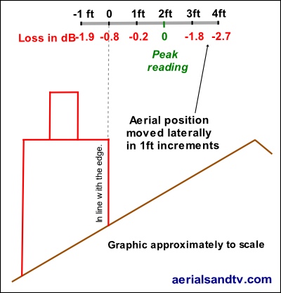
Many people know that raising an aerial in height can affect the signal level, but an aerials lateral position can also have just as much bearing on reception. I have suspected the latter for years but wanted to know just how much the signal can be affected so we set up a five foot long horizontal pole, moved the aerial in one foot increments to the side and measured the results. A length of five foot was chosen because we sell a 10ft “Supercrank” pole with an offset of about 2ft, i.e use of the latter can move an aerial around two foot sideways, either way.
This experiment more than any other shows that just because your “mate from down the road gets a good picture”, it isn’t any guarantee that you will ! That said, your next door neighbour’s signal levels are usually a pretty good indication of your own likely signal strength.
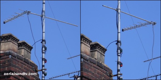
Despite the DM Log (pointed at Emley Moor) being nearly three feet above the chimney I had still expected the signal level to increase as the aerial was moved away from the stack and this is what happened. What I didn’t really expect was for it to start dropping off again as the aerial moved more than 2ft out to the side ! Another classic example of RF being a Black Art methinks.
At first I thought it was the presence of one the diagonal stay wires which we use to stabilise our mast. So at slight personal risk (you have to suffer for your art....) I climbed over the ridge and disconnected it. Result ? No difference ! Just to confirm the trend I extended the pole even further away from the stack and the signal promptly dropped even more.....
Examination of the graphic below shows that as the aerial is moving out from the stack it is also getting closer to the ridge. Despite the fact that the aerial was still 4ft above the ridge, which I’d have thought was a reasonable clearance, I still think that the presence of the roof/ridge is the cause of the fall off. I say think because one cannot know anything about RF for sure.
The graphic below doesn’t show that the aerial is pointing over the ridge towards the transmitter at about 45 degrees, I’m unsure how relevant this is but I thought I’d mention it anyway ! Gaining 2 to 3 dB by moving an aerial two or three foot is very significant. To put it into perspective that’s the increase that one would get by swapping from a 46 element wideband Tri Boom (or a Log36), to a decent grouped Yagi 18B !
Unfortunately it’s a time consuming business finding an RF “sweet spot”, and there’s no guarantee that one even exists on the installation one is undertaking. Furthermore if the antenna is pointing through trees who is to say that they’ll just grow a bit, and then you’ll have to start all over again !
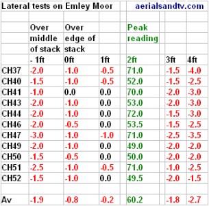
Conclusion
The lateral position of an aerial can be just as important as the vertical (height) of it in the amount of signal that it will receive. This is particularly the case in hilly areas or in the vicinity of a roof, or a chimney, etc. Also see RF is a Black Art......
Aerial Separation Tests (how far apart to mount aerials)
For those not interested in the full test report the summary / conclusion is at the bottom of the article !
Other than for diplexed antennas (or phased arrays) there should be no need for more than one TV aerial on any pole, so in some ways this article is extraneous ! However one does frequently see multiple television aerials installed on the same mast so it is of interest to find out how much signal they’re losing, if any. Obviously different aerials may give different results, but I wasn’t going to go down the route of trying it. If you imagine the number of aerials on the market how long do you think that would take !
I used two “Contract aerials”, not because I recommend them (quite the opposite in fact....) but they can be stacked close to each other because the reflectors are so small. Both of the aerials are widebands so as to test the array over the full range of frequencies.
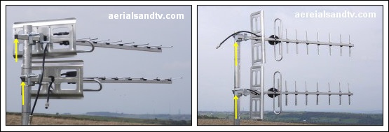
Two aerials mounted within 6” of each other. The pair on the left horizontally polarised and those on the right vertically polarised. Note how the yellow arrows show the vertical pair are in phase with each other whereas the horizontal pair are out of phase.

The results table (above) more or less tells the story, i.e. at 6” separation there isn’t that much of an effect, but that isn’t quite the whole story......
At most of the frequencies the signal levels were the same, and in fact at some they were actually up slightly, such is the black art nature of RF and aerial tuning ! Don’t forget much depends on the wavelength of the signal. However, whilst the 0.6dB average fall off in signal (over the B group frequencies) is not that large this average figure does disguise the fact that two of the frequencies (CH 37 and CH 40) were actually down by 2dB. The fact that the two frequencies most affected were so close to each other would seem to prove that signal wavelength is critical to any observed effects.
Now while it must be admitted that in the great majority of locations this 2dB loss of signal would be irrelevant, but in a really poor signal area it would be worth having.
Moving the second aerial down to 1ft separation the losses decreased significantly, in fact we’re at the limit of experimental error here, but there was still an effect. Some frequencies were up slightly and some down. I then tried moving one of the aerials so that they were out of phase, that is to say one was moved forward so the elements were not immediately below those of the other, see the yellow arrows on the pictures. This did have an effect but it was only marginal.
Finally I experimented with the both the aerials vertically polarised. Unfortunately at the test site only two of the six transmitters are vertically polarised so we’re working with less data (that’s why there’s only C/D group results) but the difference in signal levels seemed less, if anything, than with the horizontally polarised pair of antennas.
I didn’t have the time (or inclination) to test it, but if mast head amplification is involved the received wisdom is that aerial separation becomes that much more important.
Conclusions
Mounting aerials of the same polarity close to each other can have an effect on the signal, though it may only be marginal. Try to separate the antennas by at least one foot, and preferably two or three. If the aerials are of opposite polarities antenna separation is of less importance, for example, the element of a vertically polarised FM Have Wave could literally pass through the elements of a horizontally polarised TV aerial with no significant effect on the signal (see the tests on this subject).
But, as already stated, it is not normally necessary to mount multiple TV aerials anyway !
Use of cradles with log periodic aerials
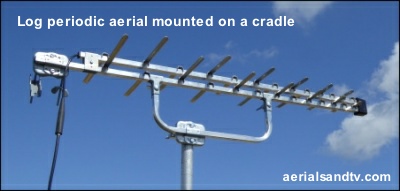
Funnily enough we get asked about this quite often, particularly by caravanners / boaters. I think it’s because they don’t want an end mounted aerial due to the fact it may overhang an adjacent pitch or the tow path, the former being for caravans and the latter for boats (unless there’s been a violent hurricane in which case they’re interchangeable…..). It’s also an indisputable fact that end mounting an aerial does produce more twisting force on the pole when the wind blows, which is why we don’t usually recommend end mounted aerials (for larger antennas), and if we do we advise using saddles with the pole. However, Log Periodic aerials are pretty low wind loading so it’s not usually a problem with installs on buildings, though, on the other hand, the average caravan aerial mounting is not anywhere near so rugged.
The received wisdom is that using a cradle with a Log Periodic is a bad idea because it can theoretically alter the impedance of the aerial. Thus, up to now, we’ve advised people to insulate the cradle from the aerial to be on the safe side. So, I bolted a cradle to a DM Log and checked the signals, the results are to the right. It’s quite obvious there is no significant difference in signal, though that is not quite the end of the story. Theoretically if the screen of the feeder (the cable) is earthed and so is the pole, to which the cradle is bolted, the signal could be affected. I’d have thought it unlikely, but if you have a cradle mounted Log and get unexplained low signal try removing it from the cradle or electrically insulating the cradle from the aerial’s boom.

Anecdotally a few of our customers have used their DM Logs with cradles and not reported any problems with lower signal level.
Note 1 : routing of the cable back up the boom can affect the signal negatively on a Log Periodic, so, if using a cradle with a Log, route the cable as far away from the aerial as possible.
Note 2 : Neither the DM Log, nor any other log periodic aerial, comes with a cradle as standard ! We do, however, sell cradles separately.
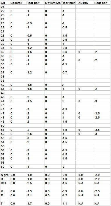
How much signal is lost using only the rear half of an aerial ?
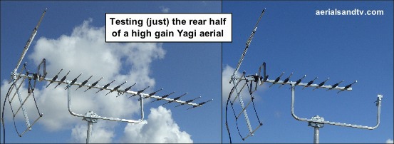
How often do you see an aerial with the front half missing ? Have you ever wondered how well it’s actually working ? On another tack, if you want to put an aerial in the loft but lack space how will it perform if you only use the rear half ?
Whilst up at the test site I farted about testing just the back half of two aerials, one of those common “Bacofoil” types (aka Screwfix / SLX) and a DY14WB. Later, on the shop roof, I did the same with an XB10B/K.
Over the two W/B aerials the approx loss (av) was :
A grp = minus 1dB
B grp = minus 1.5dB
C/D grp = minus 2dB
----------------------------------
All CHs = minus 1.4dB
Interestingly the grouped aerial lost a bit more signal, minus 2.9dB over the B group. If I had the time I could extend the tests to a load of grouped aerials to see if a trend emerged, but, to be frank, at the moment anyway, I can’t be arsed.
Conclusion
Basically the aerial loses a significant, but not massive, amount of gain, and more signal is lost higher up the band for which the aerial is designed. Remember in aerial design the law of diminishing returns (as regards extra directors for more gain) applies with a vengeance.
