Distribution systems / system work

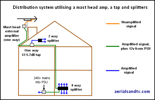
Basic distribution system using one amp and one tap

For this system we would recommend our variable gain mast head amp, in order to obtain the correct signal level. Ideally a meter should be used, and not a £30 job, even the (not entirely believable) signal levels on STBs/TVs are better than those, but at the end of the day what actually counts is how often the picture/sound breaks up, and the best signal level can usually be obtained by trial and error with the variable gain setting.
Utilising a 12/1.7 dB tap, and allowing a 2dB cable loss from the tap to the 8 way splitter, would give the following readings throughout the system (all relative to those at the input to the tap).
Side output of tap = -12dB
Output of 2 way splitter (-4dB) = -16dB
Through output of tap = -2dB Input to 8 way splitter = -4dB
Output of 8 way splitter = -16dB
(e.g. last -16dB figure = 2dB through tap loss + 2dB cable loss + 12dB eight way splitter loss)
If the mast head amp were at maximum gain, then then add 22dB to all the above readings to get the figures relative to the signal at the aerial.
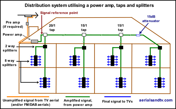
Distribution system using a launch amp, taps and splitters

For the above system a launch amp would usually be required in order to obtain the correct signal level. That said, provided the input signal was strong enough our 1 way mains amp may still do the job as it has a high maximum signal input level. Ideally a meter should be used, and not a £30 job, even the (not entirely believable) signal levels on STBs/TVs are better than those. But at the end of the day what actually counts is how often the picture/sound breaks up, and the best signal level can often be obtained by trial and error with the variable gain setting(s).
Assuming a 1dB cable loss (equating to about 10m) between each tap, and a 2dB cable loss [about 20m] between the taps and 2 way splitters, sample estimated loss figures at various points on the system (all relative to those at the input to the first tap) would be as follows:
Input to first 2 way splitter = -22dB
Outputs from first pair of 8 way splitters = -38dB
Input to second 2 way splitter = -19dB
Outputs from second pair of 8 way splitters = -35dB
Input to third 2 way splitter = -21dB
Outputs from third pair of 8 way splitters = -37dB
Input to fourth 2 way splitter = -22dB
Outputs from fourth pair of 8 way splitters = -38dB
(e.g. the -37dB figure = (2 x 1dB through tap loss) + (1 x 15dB side tap loss) + (2 x 1dB cable loss) + (1 x 2dB cable loss) + (1 x 4dB 2way splitter loss) + (1 x 12dB 8 way splitter loss))
A 3dB difference in final outputs would not usually be significant.
It will be noted that there is a 15dB attenuator before the last set of splitters (to equalise the output levels, thus it would be possible, if required, to add more splitters and therefore extra outputs. If the power amp were at maximum gain, then add 35dB to all the above readings to get the figures relative to the signal at the aerial.
System work
I am not expert in electrical or building regulations, but the last I heard the definition of "a system", under which additional safety regulations are applicable, is one which supplies points to rooms behind more than one lockable door. That is to say if all points are behind one lockable door it is classed as domestic, for which no regulations apply for TV distribution systems for earth bonding requirements, as far as I'm aware.
The most important requirement for system work is that it must be electrically bonded to the building's main earth terminal (see linked pdf). All our splitters (except the CoAx one), taps and mains amps (except the 2 way amp) have earth bonding terminals and these should be used to connect onto said earth terminal. The connection can be made anywhere on the system, or at more than one point. Incidentally, use of copper/copper satellite cable (as opposed to RG6 type) is preferable [often it is specified] for earth bonded systems because, in a fault situation (admittedly a highly unlikely occurrence.....) it's capable of carrying greater current down to earth and blowing the mains supply safety device [either a fuse or a circuit breaker]. It should be emphasised that earth bonding isn't so much about the possibility of mains currents finding their way onto the CoAx sockets as it is about preventing the “touch current” (from multiple linked double insulated - i.e. unearthed - electrical products) getting to the point where it's detectable, or uncomfortable, or even dangerous. The latter is possible but, it must be said, relatively unlikely, though it should be remembered that different people have different sensitivity to electrical currents. Some people who are more sensitive will feel a relatively minor amount of electrical current pass through them and think they've had a mains shock!
Those considering installing a system (under the definition of a system above) are advised to read the appropriate electrical code of practice.
As a bit of controversial food for thought. I have to say that speaking as a TV engineer (or more accurately an ex TV engineer) I cannot actually imagine how a TV, or an aerial amp come to that, could put dangerous voltages out of the aerial socket(s). In fact in August 2011 I phoned round 7 of our best (ex) customers [we supplied TV service manuals up to July 2010] and none of them had ever seen such a fault condition. The only possible method would be some ignoramus who knows nothing about TVs trying to mend it, and even then it'd almost certainly just blow the power supply, or just lie there dead (the TV that is). But if, by some incredible set of circumstances, a particular piece of equipment managed to develop a fault which could put mains voltage onto said socket (and I've never seen it in 15 years) I'd have thought it'd be far more likely it'd blow the fuse(s) or even blow out a PCB track.
And anyway years spent delving into the depths of TVs whilst they're switched on means I've had dozens of mains shocks * (though it's advisable not to be touching anything earthed whilst this happens though! ). What can I say ? I'm still here.
But on the other hand people do get hit by asteroids, apparently.
What does amuse me is that there are people out there who are scared stiff of getting a mains shock, but then they go speeding in their cars ! ? ! And that's far more likely to kill them.....
Whatever the likelihood of any problem, remember the golden rule : cover your arse.
* Interesting sidelight. Most people think that getting the odd shock is a TV engineer's biggest bugbear, whereas in actual fact the most painful part of being a TV engineer is getting accidental burns off the solder or the soldering iron! And they can hurt for days, not just a few seconds as the average electric shock does.
Also see : Lightning risk and aerials
CoAx cable next to mains cable
Further comment on regulations came from Mike Felton who, after reading our tests on interference problems running CoAx next to mains cable, took the trouble to inform us that it's against Electrical Regulations to run 2 different categories of cable together unless separated by a fireproof barrier. We're grateful to him for taking the time to contact us.
We've been told now, and, although I'm no electrician, it does actually sound like the kind of thing you'd find in the Electrical Regulations. However, just like the above example where in reality it'd be virtually impossible to get a mains shock from the tuner of a TV, I have to say I cannot personally think of any realistic combination of circumstances were there'd be any significant danger from running mains cable next to CoAx. Certainly not from the electric shock point of view anyway, the current would have to get through not one, not two, but three layers of insulation ! If one or other of the cables was to catch fire that would be a different kettle of fish risk wise, but if, say, the mains cable caught fire, I'd have thought any proximity it may have to a TV lead would be the least of your worries......
That said, particularly if you're not doing the job in your own home, cover your arse.

